
|
|
|
#1
 07-04-2012, 04:03 PM
|
|||
|
|||
|
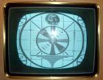
little sony dim picture
sorry cant ready the model number but its about 7" diagonal B&W rotary tuners guessing late 70's.
Pic brightness all the way up, get a barely decent pic completely cuts off at anything less than about 1/4 turn on the brightness. Beside a weak CRT (which I have not checked yet) I assume I will need to check CRT voltages for bias settings. Anything else come to mind? Last edited by DaveWM; 07-04-2012 at 04:12 PM. 
|
|
#2
07-04-2012, 05:12 PM
|
||||
|
||||
|
Check the CRT and CRT voltages. The CRT voltages need to be very close to what's on the schematic or you may have problems.
__________________
http://www.youtube.com/user/radiotvphononut
|
|
#4
07-04-2012, 07:26 PM
|
||||
|
||||
|
There's a Sony 5.5" CRT on eBay now, don't know if it's correct for your set or not.
http://www.ebay.com/itm/Vintage-Sony...item4d02a9ab4a And a 9" http://www.ebay.com/itm/SONY-9-CRT-U...item2c51fcb951 Whoops, I see you said it's about 7", well I'll keep looking.
|
|
#5
07-04-2012, 09:16 PM
|
|||
|
|||
|
http://www.ebay.com/itm/Rare-Vintage...item35bc5f55a0
here is is for sale, interesting the CRT looks about as bright as mine.
|
| Audiokarma |
|
#8
07-05-2012, 08:25 PM
|
|||
|
|||
|
Im going to email you the sams on it, its going to blow your mind
   The filament IS the cathode and it uses a little isolation transformer that looks like it may apply the horz/vert blanking too. I see a 1uf boost filter cap that could cause low boost/low G2 It is a unique design thats for sure. There are disassembly instructions in here.
|
|
#11
07-05-2012, 09:03 PM
|
|||
|
|||
|
another odd thing the contrast pot does not do much except at the extreme end so I will look at the 100uf emitter bypass cap as well. I also see a voltage divider used for the base bias, if that 9100 ohm resistor went high then the bias would be fouled up as well. think I will check C501/C503 and the C505/C508 (boost filter on the brightness you mentioned). Will also get voltage readings on that transistor and the CRT pin 1 and the anode.
|
|
#13
07-05-2012, 09:11 PM
|
|||
|
|||
|
Just to note so everyone doesnt think were too crazy here....the crt is kinda like a 5U4, The filament is the cathode so they use an isolation transformer much like you would to save a crt with a heater to cathode short. The isolation transformer is driven by the flyback.
I have a feeling this is one of those deals where they crt never goes bad or is always the problem. No way to test it.
|
 |
|
|


 Linear Mode

