
|
|
|
#16
 09-15-2015, 12:02 PM
|
||||
|
||||
|
First thing I'd do is check the B+ resistors in the vertical stages. Your setup may be similar to this:
__________________
"Restoring a tube TV is like going to war. A color one is like a land war in Asia." 
|
|
#17
09-15-2015, 12:05 PM
|
|||
|
|||
|
indeed B+ and BOOST which is where the plate of the multivibrator gets its voltage. The reason for checking the .1 is if its even a little be leaky it will drag the plate voltage down, effecting the height. I am guessing you have the height pot maxed out?
|
|
#18
09-15-2015, 12:24 PM
|
||||
|
||||
|
Quote:
|
|
#19
09-15-2015, 01:00 PM
|
|||
|
|||
|
yea so lack of height is the real issue, the linearity problem will likely resolve when you can set it correctly.
I would try in this order check line voltage (should be at least 117ac) check B+ voltage if ok try known good tubes in vert (multi and output) if no change try each testing inbetween check resistors mentioned esp the 48k or 68k from the boost to the height pot, this frequently drifts high. check the screen and plate resistors per picards post bridge the 100uf vert out cathode bypass if still an issue comeback for more. My money is on the 100uf OR the boost resistor in series with the height pot. I would also recommend replacing the .1 elmenco's there are two of them, replace them both. The pots could be bad but if the were I would think the adjustment would be jumpy and or not working. the best way to test a pot is to take it out of circuit and test with a analog meter. For now just hit them with some clean juice and work them some.
|
|
#20
09-15-2015, 09:51 PM
|
||||
|
||||
|
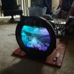
Okay so as a simple test, Tom was kind and provided me with the parts and tubes he'd removed from the set when he was working on it.
Just as a shot in the dark, I swapped out the 6JB5 tube and it did help a bit. The linearity is still off, but I don't have the set vertical height pot cranked to the max to fill in the screen, and the top isn't stretched out as much. The bottom is still compressed, but the over all quality of the picture is better. I decided to swap this particular tube, because I looked in the back of the set last night, and noticed it had a purple glow going on. The one I put in doesn't have that purple glow. I'm not sure what that glow is, but I have seen it before on 6LQ6 tubes inside of a Ham Radio RF Amplifier. When the amplifier was transmitting, the tubes would glow like that when they were driving RF. I also did a very basic purity adjustment, and I was able to clean off that green splotch on the right side of the screen. I also made the stupid newbie mistake and reached too far behind yolk assembly and got a shock/burn on one of my fingers. Whoops!
|
| Audiokarma |
|
#21
09-15-2015, 10:44 PM
|
|||
|
|||
|
yoke burns are PAINFULL, much worse than HV, more current available I suppose.
Just remember that that purity and convergence setup are effected by sweep so if you go thru the effort to adjust those before fixing sweep, you will prob just have to do it again when/if you get the deflection working. process in this order AFTER the set has been on for 20 min to warm up. full raster (vert and horz) setup linearity with test pattern purity best reds (yoke back/center red blob/yoke forward to best fill red) center converge (dots) focus for sharpness and keep the brightness down dynamic converge (cross hatch) grey scale
|
|
#22
09-16-2015, 12:37 AM
|
||||
|
||||
|
Quote:
Because I didn't like how the tube looked, I swapped the 6JS6 Horizontal Sweep for a 6KD6 spare I had. Another huge difference. It did not help the current issues but it did sharpen the picture up a ton. It always seemed slightly dim before and a little out of focus. The 6KD6 made a big difference.
|
|
#23
09-17-2015, 06:05 PM
|
||||
|
||||
|
Overall, other than the linearity and the blueish screen, you've got a winner there.
When I used to set up the screen controls with the service switch, I'd bring up red first to be almost dim... I did mine in a darkened room... Then the blue to make the red line purple, and then the green to make the grey. That should get you close. Forgot to say, turn the color and brightness all the way down first.
__________________
Bruce
|
|
#24
09-21-2015, 10:36 PM
|
||||
|
||||
|
Does anyone know what the difference with a 6JS6A and 6JS6C Horizontal Output is?
I didn't pay close attention to the letter and stuck in a C instead of an A. It works, but I wonder if that's why the tube it self acts weird until it warms up?
|
|
#25
09-22-2015, 05:11 AM
|
|||
|
|||
|
If you haven't already, Defo worth replacing C5 and C6 in your vert O/P stage.
Leccy-lytics lose value and dry up over the years, and in vertical timebase have a pretty hard life. Any high value resistors in Height and Linearity control networks are also suspect. Poor vertical lock could be issues in the sync-separator circuit, look for bias resistors of around 2.2M (Common issue on a couple of UK Hybrid TV sets, guess much the same applies if you have a Transistor doing sync-sep in yours) A tip that was told me when I started out as a Trainee 40 odd years ago for setting up Any color TV.... Get the picture as good/perfect on Black/White First, Then worry about color after--Or you'll chase your tail! --Its worked out pretty darned well during the last 40 years for me--so there must be summit in it!
|
| Audiokarma |
|
#26
09-22-2015, 10:49 AM
|
||||
|
||||
|
Quote:
jr
|
|
#27
09-22-2015, 01:43 PM
|
||||
|
||||
|
Okay so per recommendation I am replacing the electrolytic caps in the vertical section.
I was able to get a couple from Chesters today but I have run in to a bit of an issue; C5 has two sections in it that are rated at 475V, 50uF and 40uF respectively. Chesters only had caps that went up to 450. Same for Capacitor World. Where would I source these from?
|
 |
| Thread Tools | |
| Display Modes | |
|
|


 Linear Mode

