
|
|
|
#16
 09-08-2013, 04:09 PM
|
||||
|
||||
|
I'm trying to locate the three diodes in the horizontal circuit and easily found the one on the horizontal output. Here's the thing. The one on the output (CR218) looks just like a diode should (as far as my knowledge goes they're cylinders) and so does the boost (CR219). However, the other boost (CR221), which is the same part number as the other two, looks completely different. It's similar, but looks pregnant. Is this the same thing, and just an different manufacturer?
I'm attaching an image of what I found in the place the SM says is the CR221 (part # 103-193).
__________________
Pioneer SX-1080, Pioneer PL-115D, Pioneer CT-F9191, Pioneer RG-1, Wollensak 8050A, Akai 4000DS MkII, Pioneer CS-05 & Polk 1.2TL Denon 5803A, Pioneer DVL-700, Pioneer CT-W603RS, Toshiba HD-A3, D-Link DSM-520, Dish VIP-722, Polk 1.2TL, CSi5, LS/fx, RT-800 and PSW-650 Last edited by TinCanAlley; 09-08-2013 at 04:13 PM. 
|
|
#17
09-08-2013, 04:48 PM
|
|||
|
|||
|
Yes, that sure is a diode. Now I'll throw my two cents in... it sure looks like you have a 'ring' in there somewhere... have you checked the yoke for any caps??? It would be a perfect L-C circuit to oscillate... just a thought. I'll make it four cents... take a trip to a hamfest and buy a decent triggered scope with a calibrated timebase and some high zoot probes... sure would make life easier!!
Best of Luck!! Jim
|
|
#18
09-08-2013, 04:54 PM
|
||||
|
||||
|
Quote:
Figures, the Hamfest here is this month and I'm not able to go those days. So any idea why that diode looks completely different than the other two when they all have the same part number?
__________________
Pioneer SX-1080, Pioneer PL-115D, Pioneer CT-F9191, Pioneer RG-1, Wollensak 8050A, Akai 4000DS MkII, Pioneer CS-05 & Polk 1.2TL Denon 5803A, Pioneer DVL-700, Pioneer CT-W603RS, Toshiba HD-A3, D-Link DSM-520, Dish VIP-722, Polk 1.2TL, CSi5, LS/fx, RT-800 and PSW-650
|
|
#19
09-08-2013, 05:18 PM
|
||||
|
||||
|
Most likely a different manufacturer, same ratings. My 75 Chromacolor II has several of those little bead Diodes as well as some regular barrel type.
|
|
#21
09-08-2013, 05:57 PM
|
||||
|
||||
|
This really is a job for a first class scope.
Look at the video output to the picture tube and the input to the horizontal output tube. Also examine the output of the horizontal output tube BY HOLDING THE PROBE CLOSE TO THE PLATE LEAD but NOT touching it. Look for the ringing. Then simply remove the horizontal output tube and see what happens to the waveforms. Make sketches of the waveforms and report back. Use the grid of the horizontal output tube for sync of the scope. If its an AC-DC set you can't pull the horizontal output tube ... in that case, disconnect the plate cap lead. That's the first step.
|
|
#22
09-08-2013, 06:05 PM
|
|||
|
|||
|
its a zenith solid state, so don't pull anything to test with it running.
I agree with the others about the use of the scope, this gets back to having a scope and a lot of knowledge to know how to use it. With out it I was taking a guess at the damper. I don't have a lot of exp with SS sets, so take it for what its worth.
|
|
#23
09-08-2013, 06:07 PM
|
||||
|
||||
|
Quote:
__________________
Pioneer SX-1080, Pioneer PL-115D, Pioneer CT-F9191, Pioneer RG-1, Wollensak 8050A, Akai 4000DS MkII, Pioneer CS-05 & Polk 1.2TL Denon 5803A, Pioneer DVL-700, Pioneer CT-W603RS, Toshiba HD-A3, D-Link DSM-520, Dish VIP-722, Polk 1.2TL, CSi5, LS/fx, RT-800 and PSW-650
|
|
#24
09-08-2013, 06:09 PM
|
||||
|
||||
|
Quote:
Why don't any of you experts live in SoCal. 
__________________
Pioneer SX-1080, Pioneer PL-115D, Pioneer CT-F9191, Pioneer RG-1, Wollensak 8050A, Akai 4000DS MkII, Pioneer CS-05 & Polk 1.2TL Denon 5803A, Pioneer DVL-700, Pioneer CT-W603RS, Toshiba HD-A3, D-Link DSM-520, Dish VIP-722, Polk 1.2TL, CSi5, LS/fx, RT-800 and PSW-650
|
|
#25
09-08-2013, 06:15 PM
|
||||
|
||||
|
I'm going to flip her over and check out that diode. Want to make sure it's the right one for the job. I would imaging there's some kind of part number on it.
__________________
Pioneer SX-1080, Pioneer PL-115D, Pioneer CT-F9191, Pioneer RG-1, Wollensak 8050A, Akai 4000DS MkII, Pioneer CS-05 & Polk 1.2TL Denon 5803A, Pioneer DVL-700, Pioneer CT-W603RS, Toshiba HD-A3, D-Link DSM-520, Dish VIP-722, Polk 1.2TL, CSi5, LS/fx, RT-800 and PSW-650
|
| Audiokarma |
|
#26
09-08-2013, 06:27 PM
|
|||
|
|||
|
|
|
#27
09-08-2013, 06:52 PM
|
||||
|
||||
|
Quote:
I'm trying one last source for NOS, if not, RS has them for 2.50 each w/free shipping. That's cheaper that all other sources that want about 1.30 each, but roughly $9 shipping.
__________________
Pioneer SX-1080, Pioneer PL-115D, Pioneer CT-F9191, Pioneer RG-1, Wollensak 8050A, Akai 4000DS MkII, Pioneer CS-05 & Polk 1.2TL Denon 5803A, Pioneer DVL-700, Pioneer CT-W603RS, Toshiba HD-A3, D-Link DSM-520, Dish VIP-722, Polk 1.2TL, CSi5, LS/fx, RT-800 and PSW-650
|
|
#28
09-08-2013, 07:37 PM
|
||||
|
||||
|
You need to get off the diodes, If it is a diode, not likely, you will have to replace it, they will test ok, but this problem is showing up at a frequency you can't replicate with a tester out of circuit.
Its some decoupling cap, or an RC, LC, circuit. Most likely an LC, yoke, possibly, High Voltage transformer greater likelyhood, Decoupling cap, some cap near an LC circuit running to ground. There are caps with a mark indicating "outside foil" this in most cases went to ground, when you recapped, did you replace using marked "outside foil" caps, and put them in the right way? (These will not be electrolytic caps, but the smaller caps.) This can be a cause of interference. If you use a scope to try and find this, it will have to be a good one to see the ringing, it will be a pretty high frequency. You will have to have a good probe, and it will also have to be calibrated to the square wave test point on the scope, that way your probe does not effect what you are looking at. And someone said grounds, look at grounds if there was someone in there before you doing poor solder joints.
__________________
Yes you can call me "Squirrel boy" Last edited by Username1; 09-08-2013 at 07:50 PM.
|
|
#29
09-08-2013, 07:51 PM
|
||||
|
||||
|
Quote:
Do you have access to the Sams for the 25EC58 chassis? I think if you could point out where and LC or decoupling cap is in the horizontal circuit, that would help greatly. I think I understand the concept, but unsure when I look at the schematics. I see a 15ohm coil on the boost line and to a .47 cap to ground. Am I looking at the right stuff? I'm still quite green with all of this, so hang in with me. 
__________________
Pioneer SX-1080, Pioneer PL-115D, Pioneer CT-F9191, Pioneer RG-1, Wollensak 8050A, Akai 4000DS MkII, Pioneer CS-05 & Polk 1.2TL Denon 5803A, Pioneer DVL-700, Pioneer CT-W603RS, Toshiba HD-A3, D-Link DSM-520, Dish VIP-722, Polk 1.2TL, CSi5, LS/fx, RT-800 and PSW-650
|
|
#30
09-08-2013, 08:23 PM
|
||||
|
||||
|
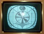
The moire' patterns occur where the focus is a little too sharp and the scan line structure beats with the CRT screen structure. You can show this easily by adjusting the focus in and out or even by adjusting the vertical linearity or height slightly to change the line spacing. Nothing can be done to fix this.
Regarding the jail bars: I lost track of what set this is and how it's constructed. If it has more than one printed circuit board, make sure all the boards are well grounded to the chassis at their ground points. The ringing frequency will be well within the capability of almost any scope - it looks to be 10 or 12 times horizontal, so that's 200 kHz at most. The problem is, if it's getting into the video and caused by ground currents, the scope would need to be hooked to the same ground point and hot point as the video circuit to see whatever the video circuit is seeing. So, you have a huge number of possibilities of how to hook up your scope. Also, it may be difficult to see if it's getting in at a low-level point in the video circuit and your scope does not have much gain. As others have said, it might not be in the video, but on one of the CRT electrodes. Does the strength increase and decrease as you turn the contrast (picture) control? If so, it's in the video. If not, it may be getting to the CRT through some other path, or getting into the video after the contrast control. If there are multiple printed circuit boards (or just multiple ground points on one board), it may be worthwhile to connect some of them to each other or to the chassis with ground wires and observe what happens to the jail bars when you do so. You may find some hot spots this way. Good luck!
|
| Audiokarma |
 |
| Thread Tools | |
| Display Modes | |
|
|


 Linear Mode

