
|
|
|
#1
 07-23-2011, 06:12 PM
|
||||
|
||||
|
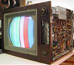
CTC2B Component Video Monitor
CTC2B Component Video Monitor
Now that the 21CT55 's PQ is at least as good as it was before the FBX meltdown I intend to resume my implementation of 400 line resolution component video processing in addition to the present 256 line resolution composite processing, hopefully. I have been off and on modifying my 21CT55s CTC2B chassis to process external component video since January 2010. The CTC2B seemed the ideal candidate since it uses low-level matrixing and has potentially >4mhz bandwidth video CRT drivers. I have progressed to the level of working out all the required interfacing and have constructed one of three RGB channels feeding the three CTC2B CRT driver boards. I have all the notebook entries complete with waveforms to finish the switchable dual composite / component CTC2B chassis. Seems the three components: Y, Pr, and Pb, are available on three of my DVD players. Y is the luminance with sync that has no 3.58mhz chroma messing it up so it can extend the baseband to 5mhz which equals over 400 lines resolution, where all our roundys cut off at 3.2mhz or 256 lines! I think I can extend my 21CT55's original final three stages of CRT drivers to possibly 5mhz without chroma interference. It would be great to see the resolution chart wedge with its lines displayed to 400 lines without all the chroma artifacts we see now. My CTC2B chassis is not constrained by the "restoration" consideration and has never processed the deceased NTSC RF/IF programmed inputs. It has always performed as a pure composite video monitor, driven from DVD, Laser Disk and S-video VCR. The CTC2B has always utilized a solid-state external video op-amp that provides a "perfect" DVD quality 480 line resolution, 75ohm, 3vpp signal into the 2Bs 1st video amp grid. It also supplies the same 75ohm video at 1vpp to my two comb-filtered Sony monitors and a Leader waveform monitor. Two external video sources can be selected with a toggle switch, each with individual level and offset controls. Presently I run a DVD player with the DVE test disk into one input and a second DVD player with JPG picture playback capability into the second input. Both composite and component video outputs are available from both DVD players for comparison purposes. Last edited by Tomcomm; 07-23-2011 at 09:10 PM. 
|
|
#2
07-24-2011, 01:47 AM
|
||||
|
||||
|
Tom, I have always enjoyed your descriptions and pictures of your unique CTC-2B TV and the experiments you have done. Here is one of my thoughts: Since a component (Y/R-Y/B-Y, also called Y/Pr/Pb) input will need to be matrixed differently from the original Y/I/Q demodulated signals, have you considered trying to create a true RGB input on that set? In terms of displaying the purest/most direct input-to-CRT picture, RGB has to be the cleanest path since it involves no matrixing at all, would you agree?
There are definitely 15.734 kHz RGB-output DVD players and other devices available; let me know if you want to follow this idea.
__________________
Chris Quote from another forum: "(Antique TV collecting) always seemed to me to be a fringe hobby that only weirdos did."
|
|
#3
07-24-2011, 11:20 AM
|
||||
|
||||
|
Componant vs RGB video
Converting the CTC2B to accept RGB video inputs is no challenge. It already develops RGB baseband in its low-level matrix on the three CRT driver boards. My three component decoder piggy-back boards simply switch-replace the composite matrix RGB from the chroma demodulator, allowing dual composite/component operation. Non of my video sources, DVD, Blu-ray DirecTv have RGB outputs, they all have composite and component.
|
|
#5
07-24-2011, 01:03 PM
|
||||
|
||||
|
Wide BW shadowmask aliasing
Quote:
Surely RCA in the early '50s ran direct camera RGB on their pro monitors using delta CRTs at resolutions approaching 400 lines? The results of these tests are probably contained in some confidential RCA Lab reports somewhere. Last edited by Tomcomm; 10-26-2015 at 04:25 PM.
|
| Audiokarma |
|
#7
07-24-2011, 05:51 PM
|
||||
|
||||
|
Digital comb filters in roundys
Quote:
|
|
#9
07-24-2011, 09:40 PM
|
||||
|
||||
|
Quote:
The tough part of all of this is making 2 custom delay lines, because with component the color gets to the CRT before the luma does. Blue is less noticable than red is, since there's a greater proportion of red in almost every scene. What's needed are a pair of properly terminated delay lines, whose delay is custom tailored to the set in question. Since there will be a voltage drop across the line, another stage of amplification will likely be needed. I'm experimenting with 6GH8 (yeah yeah, they are laying around) pentode sections to preamplify the signal before it's sent through the line, but it's not an exact science. Ghosting is a big problem, as is crosstalk. The entire thing must be designed correctly or the result will be horrible. But if and when I get it right, the result will be nothing less than spectacular. Perfect convergence, luma to 4Mhz with no dot crawl, and color with digital accuracy. It will rival the picture quality of any NTSC set, including my CT55. Pretty ridiculous for a set I got for free. 
__________________
Evolution... 
|
|
#10
07-25-2011, 12:07 AM
|
||||
|
||||
|
Seems to me that an electronic adjustable delay would be necessary. The higher resolution will mean that the delay is more critical. Hence I figure it would have to be adjustable for best results.
Terry
|
| Audiokarma |
|
#11
07-25-2011, 12:34 PM
|
||||
|
||||
|
Componant differential delay
Quote:
A properly designed component video monitor will in turn process the three input analogs in identical full 5mhz BW and apply them as RGB to identical full BW CRT driver amps. Since Y, Pr, Pb and resulting RGB are processed the same there is no need for any delay lines, analog or digital to correct differential delay. Last edited by Tomcomm; 10-26-2015 at 04:11 PM.
|
|
#12
07-25-2011, 03:35 PM
|
||||
|
||||
|
The extra delay compensation was implied for your monitor. I suspect you would want to have a low pass filter in the luma and chroma paths. But then maybe that will not be necessary if the filtering is done at the source.
Or did I miss something? Terry
|
|
#13
07-25-2011, 04:04 PM
|
||||
|
||||
|
Quote:
OK, I must be wrong then. Let me know how that works out for you.  You still have a luma delay, don't you? What do you think that does to the coincidence of luma and chroma at the CRT? Trust me, it's not as simple as removing the luma delay, either. There are time shifts happening in the luma channel as well as chroma, if you don't do anything it's not gonna end up at the same place at the same time.
__________________
Evolution...
|
|
#14
07-25-2011, 05:35 PM
|
||||
|
||||
|
Quote:
I'll try again!  ............ ............The DVD player outputs R-Y as rP and B-Y as bP in perfect time registry with each other and the luma/sync as Y. The DAs that make the Y, rP and bP have responses well greater than 5MHZ at the DVD outputs. If the three coax cables leading to the CTC2B monitor are matched, perfect time registry is retained as they enter directly into the new Component to RGB converter piggy-back boards. The analog processing on these converter boards uses all ultra high speed SS video op-amps spec'd at 400mhz, 400V/us, 25ns rise time.The only signal the original CTC2B works on is the Y luma/sync and this goes direct to the sync separators and retrace blankers no place else. The RGB videos from the converter boards go directly to the original red, green and blue full BW CRT driver board's first stage grids. So is the possibility for time registry errors existing at the CRT socket real? I think not. Last edited by Tomcomm; 07-25-2011 at 06:20 PM.
|
|
#15
07-25-2011, 06:31 PM
|
||||
|
||||
|
Quote:
 It would seem to me this may be a recipe for alias artifacts. Then again, I may be wrong. I would consider filtering at least to ITU R601 specifications eg approximately 5.5 MHz for luma and 2.75 MHz for chroma. Terry
|
| Audiokarma |
 |
|
|


 Linear Mode

