
|
|
|
#196
 08-14-2019, 02:29 PM
|
||||
|
||||
|
When the Westy arrives to me, I plan on checking with a blue filter and ISF patterns.

|
|
#197
08-14-2019, 03:20 PM
|
|||
|
|||
|
I know these can't be run all that bright and that's fine with me. Pretty much every picture of an operating 15GP22 set does have that distinctive yellow color bar, including my own set. I'm sure mine is in need of tweaking and I hope I can get a proper color bar signal to use when the time comes. There is an adjustment procedure from Westinghouse when a color bar signal is not available that should get close, but it involves injecting a signal into the video path at some point, which may need to be done with the CRT off the chassis.
__________________
Erich Loepke
|
|
#198
08-14-2019, 04:55 PM
|
||||
|
||||
|
Quote:
|
|
#199
08-20-2019, 01:14 PM
|
||||
|
||||
|
UPDATE, AUGUST 19, 2019, DAY 380
Author: The “cooking” process started and the first skeletons appear … From Mike: “Hi Marshall. I have been running the set from time to time when I am in the shop. Tonight I noticed that one of the damper tubes had no filament. The tube tested fine so the issue is either a bad socket or connection somewhere. The set has qty 2 damper tubes in parallel and it will work with only a single tube but it was designed with both in order to handle the current in the flyback properly. Glad I saw this. Not a show stopper, just another “skeleton” that I am glad I found. More later, OK, there was in issue with one of the damper tube filaments going dead. The problem is the way the ground takes place on the socket. The method is standard design and the problem is from age and poor soldering techniques during production. Pin 8 (filament) of both of the damper tubes are grounded by virtue of a rivet and solder connection at the mounting point of the socket. This method works fine for a while, usually through the “warranty period”. LOL. Then, the electrolytic action caused by the difference between the two metals causes some corrosion. As long as the solder connection between the two is good then everything is fine. But that was not what was happening in this case. The parts were not cleaned well enough and the corrosion, even though a small amount, was enough to cause enough resistance to keep the filament current from flowing. So, the fix is to install a wire from pin 8 of each of those tubes to ground and soldered well at both ends. This fixes the problem forever. Pix #1 Pin 8 and the rivet in the center of the shot. You can see the poor soldering job and the circle around the rivet proves that the solder did not flow properly. Pix #2 The other damper tube pin 8 soldering job also doomed to fail. Pix #3 The repair. The black wire connected to both pin 8’s and terminated to the chassis at a good solder point. Stay tuned. Mike.” https://visions4netjournal.com/westi...-carousel-9993 
Last edited by etype2; 08-20-2019 at 10:16 PM. Reason: Typo
|
|
#200
08-20-2019, 03:44 PM
|
|||
|
|||
|
Maybe there were quality problems with these sets as mine also had several bad solder joints that I know of. One was on the 410V B+ line, killing the sweep oscillators and horizontal output intermittently, also causing an arc at the red screen control which had to be repaired using india ink on the end of the resistance track. The other one I found so far was a terminal strip ground in the color amplifier section which lifted the cathode circuits of the red, green, and blue amplifiers, also intermittently.
__________________
Erich Loepke
|
| Audiokarma |
|
#201
08-20-2019, 03:54 PM
|
||||
|
||||
|
Quote:
|
|
#202
08-20-2019, 04:16 PM
|
|||
|
|||
|
Not too many problems in the HV cage except for high leakage in two of the doorknob capacitors which killed the HV supply nearly completely. No arcing even when the HV regulator wasn't doing anything and I was getting 27KV out of it. My set is a later production chassis with 3A3 tubes in place of the 1B3s used originally. In fact the tube label in the cabinet has the 1B3 scribbled out and 3A3 rubber stamped next to it. The other big change was the addition of 4.5MHz traps in the video amplifier.
__________________
Erich Loepke
|
|
#203
08-27-2019, 03:02 PM
|
||||
|
||||
|
UPDATE, AUGUST 27, 2019, DAY 388
From Mike: “Greetings Marshall. After spending a few nights doing some modifications to the convergence circuits I am now claiming that it is as good as it will ever be. You might recall that the Vertical Dynamic Convergence transformer that we purchased is not a direct replacement for either the CT100 or the Westy, but an averaged value to satisfy both. The blue near the top continues to be a problem but it is better than when I started. I will get a screen shot to you soon. On another note, I need to order another set of H.V. rectifier tubes to try because the high voltage seems to drop a bit after the set runs for a while, like 20 minutes. It starts out fine but drops to 18 KV or so after a good warmup. These tubes are 1B3’s and it is a set of 3. I replaced them with a matched set of Mil Spec type early in the restoration process. Then there were a series of issues with arcing that I had to deal with so what I am hoping is that perhaps one of them suffered some damage during those times of arcing. I won’t know until I try new ones. I have ordered them but was unable to find Mil Spec types,, Just New Old Stock. Stay tuned! Regards, Mike”
|
|
#204
09-02-2019, 05:20 PM
|
||||
|
||||
|
While waiting for the new 1B3s, Mike fixed a broken knob. The tone control is little used, so should not be a problem.
UPDATE, SEPTEMBER 2, 2019, DAY 394 From Mike: Hi Marshall. I am working on other small things while I am waiting for the new HV rectifier tubes. So, here are the images of my repair for the tone control knob. I believe that you have the volume/on/off and channel select knobs and they have been re-plated. Question: Are these knobs that I have here which are white in color supposed to be gold in color? This tone control knob looks like it was gold at one time. If so, I can shoot them with some paint to make them match. Let me know if you learn anything about that. Photo #1 First step. Re-attaching the broken piece to the main part using JB Weld epoxy Photo #2 The first real layer of epoxy over the repair. Photo #3 I used electronic lacing tape (very strong stuff) , tightly tied around the previously broken part for added strength. Then added a second layer of epoxy. Photo #4 Finished and ready to re-install the circular spring. Not real pretty, but likely wont break again. And nobody sees this part. The other white knob is for fine tuning and they will both be cleaned with a solution of dish soap and water using a small brush. There are two other knobs which are plastic and gold in color and may need polishing. I will be careful if I attempt to do so. West 32 coming soon. Mike. 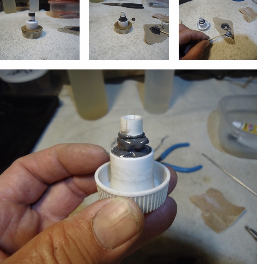
|
|
#205
09-03-2019, 02:37 PM
|
||||
|
||||
|
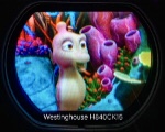
Update from Mike. You can see the problem with the convergence at the top of screen. We installed a hybrid VCT with average values for both the Westy and CT-100. The yellow band is a camera artifact.
UPDATE, SEPTEMBER 3, 2019, DAY 395 “I have been doing detail work. The 300 ohm twinlead that connects the tuner to the back cover was in very bad condition. I have replaced it and given it a path up and away from the chassis. This keeps frequency coupling issues to a minimum. Once again, I used electronic lacing tape to provide the strain relief. Also, a screen shot of the convergence. Still waiting for the new HV tubes. I believe they should arrive on Wednesday. I am a bit concerned with the lack of contrast at times. I will be replacing the video detector diode in the next report. This diode is buried inside a copper can. Pix #1 The new 300 ohm twinlead path. Pix #2 The screenshot of the convergence. Still issues with the blue. Cheers, Mike” 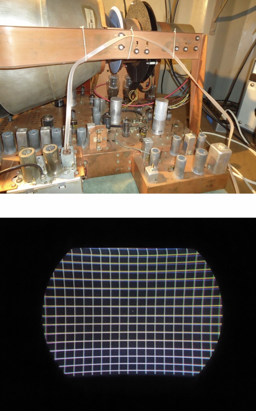
|
| Audiokarma |
|
#206
09-04-2019, 08:02 AM
|
|||
|
|||
|
My gut feeling is that convergence is going to be a compromise at best on these sets since they don't have all the separate adjustments of the later sets with magnetic convergence.
__________________
Erich Loepke
|
|
#207
09-04-2019, 12:24 PM
|
||||
|
||||
|
Quote:
ones separate for each channel. There are 6 for the yoke position and two for the purity magnet. These are ultra critical for essentially perfect convergence, which is actually achievable! My CT-100's CRT died and I now feed the signals into a pro-grade Sony 13 inch monitor. Its convergence is worse than CT-100 had ... which is still very very good, just not perfect like the best CRT computer monitors.
|
|
#208
09-04-2019, 03:26 PM
|
||||
|
||||
|
The convergence problem is at the top, so it won’t affect news banners typically displayed at the bottom of the screen. Our point, we believe the hybrid VCT may be why we can’t achieve “perfect” convergence.
|
|
#209
09-05-2019, 01:42 PM
|
||||
|
||||
|
New update
The screenshot below is compressed. See full resolution here: https://visions4netjournal.com/wp-co...DF909EA1B.jpeg
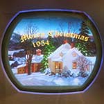
UPDATE, SEPTEMBER 5, 2019, DAY 397 From Mike” “Upon receiving and installing the new H.V. rectifier tubes, the High Voltage is now, once again, very stable at all brightness levels. YAY. And I have installed mesh screen where the panel was missing on the side of the cage. I could not get a good image of it due to the meshwork. Not sure why. And, I am still not happy with the contrast levels, especially when operating from DVD. The images with antenna TV are mostly acceptable but the contrast control is always rotated all the way up. I would like to get a bit more video drive out of this set if possible. I have decided to go in to the sealed copper can where the video detector diode is, and replace it. Pix #1 and pix #2 After removing a copper shield on the bottom of the chassis, and disconnecting 2 wires, some screws and desoldering, the can is removed from the chassis. Pix #3 The video detector diode from 1954. Pix #4 The new “all glass” version from 2019. Pix #5 The can re-soldered, sealed. Pix #6 and pix #7 Re-soldering to chassis. Pix #8 Re-solder 2 wires on bottom of chassis. Pix #9 Resoldering the shield/cover on the bottom of the chassis. Pix #10 Screen shot Although I feel very good about replacing the video detector diode, since they can be problematic, only a slight increase in contrast has been gained. I will be taking yet another look at what I might be able to do within the video amplifiers in an effort to squeeze a little more contrast out of the set. The photo of the screenshot show up much better then they really are.” 
|
|
#210
09-05-2019, 02:38 PM
|
||||
|
||||
|
Just a follow up. The screenshot scene is a dark one just after talking with the witch. He turned the brightness down for a balanced image. Mike told me that his DVD player, images look darker than broadcast television shown on post #188
Last edited by etype2; 09-05-2019 at 02:46 PM.
|
| Audiokarma |
 |
|
|


 Personal website dedicated to Vintage Television


 Linear Mode

