
|
|
|
#31
 01-09-2011, 09:54 PM
|
||||
|
||||
|
Glad to see it is coming along. In mine, at least one of the bakelite blocks only had a mica cap in it, so I left that one be, as it didn't test as leaky. I'll be curious if you can get the dial to track properly, as mine is about 50kc off on the low end of the dial, the trimmers just wouldn't compensate that far, but reception was excellent, better than a comparable Atwater Kent that I have.

|
|
#32
01-09-2011, 10:56 PM
|
||||
|
||||
|
There are several 110 pF micas in the bakelite blocks. I already picked up replacements so figure I'll go ahead and use them. I hope to fire it up in a few days.
|
|
#33
01-11-2011, 09:07 PM
|
||||
|
||||
|
I've finished unmounted and unstuffing all the bakelite block capacitors. Also the tone control and metal box cap.
  It actually wasn't all that bad. Next, I'll clean up the tubs and mount new caps inside. 
|
|
#34
01-12-2011, 07:29 AM
|
|||
|
|||
|
Hi bandersen,
I just saw your latest video--great stuff, as usual! If I remember correctly, the depth--and therefore the "mesh"--of the tuning capacitor plates can be easily tweaked using that nut/screw arrangement on the back. It is an adjustment used to change the point at which that single rear ball bears vertically on the end of the rotor shaft. Tightening the screw pushes the ball and rotor forward, and vice versa; the nut locks it in place when everything is nice and centered. Last edited by GuyIncognito; 01-12-2011 at 07:37 AM.
|
|
#35
01-12-2011, 01:07 PM
|
||||
|
||||
|
Quote:
|
| Audiokarma |
|
#36
01-13-2011, 12:43 PM
|
||||
|
||||
|
I've restuffed the block caps with the aide of all the great info at philcoradio.com
I don't see any point in refilling the tubs with anything since the open side faces the chassis.  The 8035-D was confusing though. It doesn't match what philcoradio.com showed. It also doesn't follow the usual wiring where both caps are connected to the lug terminal. Instead, the terminal opposite the lug is the common terminal. 
Last edited by bandersen; 01-13-2011 at 01:37 PM.
|
|
#37
01-13-2011, 08:09 PM
|
|||
|
|||
|
Quote:
|
|
#39
01-14-2011, 09:58 PM
|
||||
|
||||
|
Quote:
Quote:
Speaking of schematics, I couldn't find this gooey looking thing on mine. I did a little research and discovered that it's a wavetrap added to later revisions. The bubbling goo appears to be old wax.  Here's the rebuilt metal box cap. 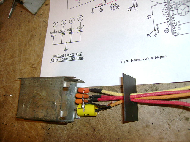 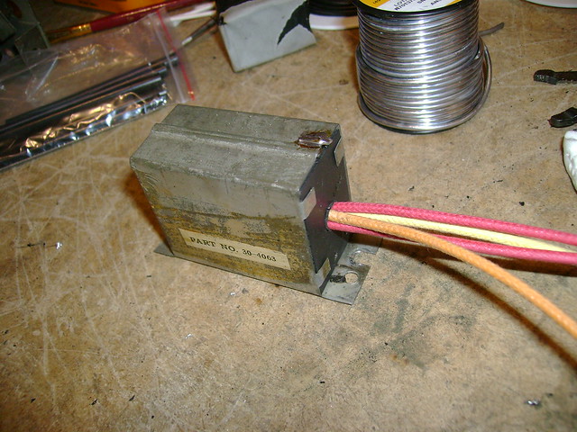 Call me crazy, but I don't like rust. So, I unmounted the power transformer and removed the clamshell covers. 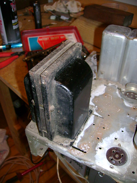 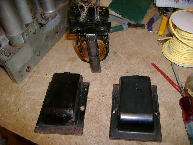 Then, I removed the rust and sanded them a bit. 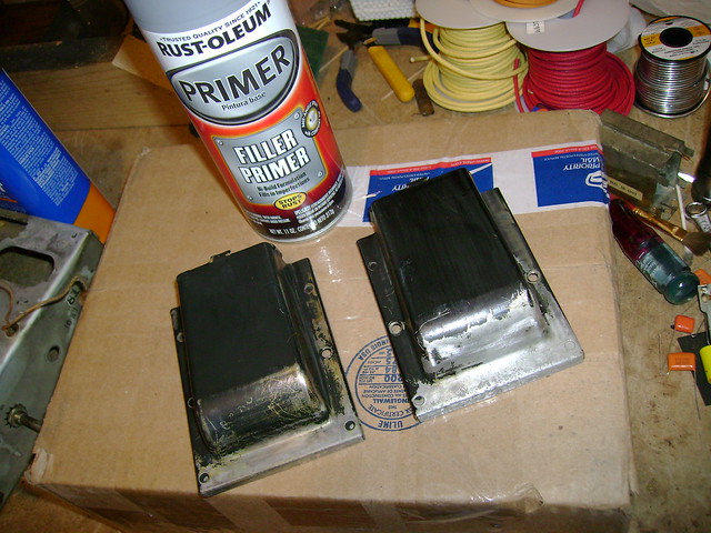 Here they are after some primer. Next up, some black enamel. 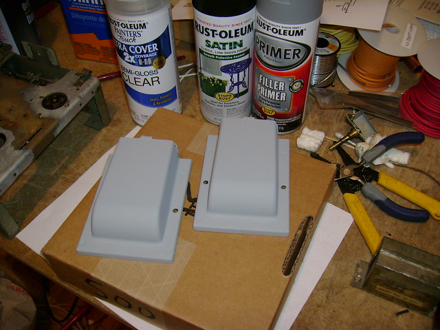
|
|
#40
01-14-2011, 11:53 PM
|
||||
|
||||
|
Oh yeah, that web site on the progression of circuit changes in the Philco model 60 is essential. From that, I was able to determine mine was the last revision.
On the Nostalgiaair website, there is an article: The Philco Model 60 Repair That Almost Wasn't, where the poor guy basically goes to recap the thing, says, hey- this radio has some weird changes, and alters his Philco back to the original style, only later realizing that those changes were intentional!
|
| Audiokarma |
|
#41
01-20-2011, 05:23 PM
|
||||
|
||||
|
Ouch! I've taken loads of photos and taken notes so I should be able to get it back together properly.
I finally got all the rust off the chassis then applied some Rustoleum "Rusty Metal Primer". I'll go a few rounds of sanding and primer to fill in the pits. The cadmium plating was fine in the unpainted areas. I also popped out the two rivets holding on the IF coil shields so I can replace the rotting grid cap lead. It makes it easier to paint around too. 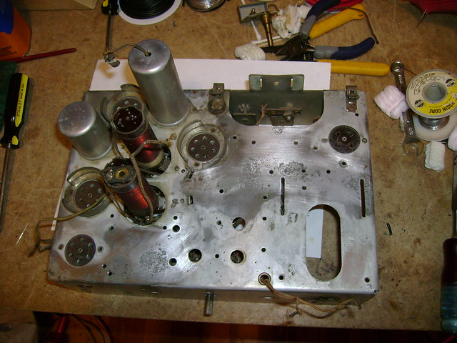 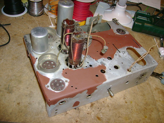
|
|
#42
01-24-2011, 11:48 PM
|
||||
|
||||
|
The original electrolytics are rated 8uF @ 475 VDC. I'm using 10uF @ 500 VDC. I think that will be close enough.
I cut the ends open using a hacksaw and found this inside. I wonder what compound those crystals are ? Nothing horribly toxic I hope  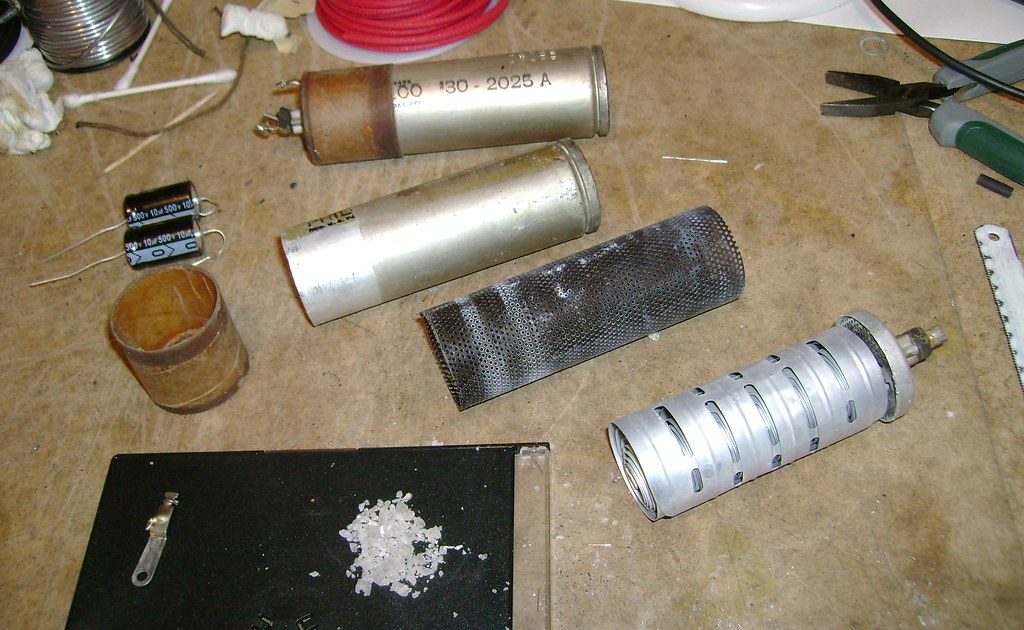
Last edited by bandersen; 01-24-2011 at 11:51 PM.
|
|
#45
01-26-2011, 03:06 AM
|
||||
|
||||
|
Quote:
I pretty much rebuilt these the same way as Phil Nelson. I did drill a small hole for the negative lead though. After feeding the lead through, I wrapped it around the old terminal and soldered it. Originally, it made contact with the can just by pressure. 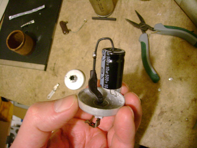 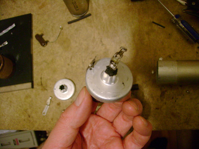 The decals were already worn off one can so I didn't mind polishing them up. While doing so, I noticed that one can is stamped 61115 and has a flat top while the other is 61116 and has a rounded top. The 61116 can also had some liquid remaining inside so maybe it's a really old replacement ? 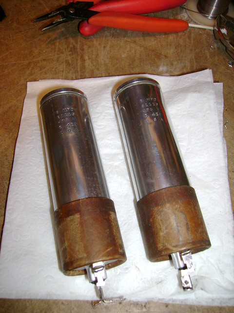
Last edited by bandersen; 01-26-2011 at 03:12 AM.
|
| Audiokarma |
 |
|
|


 Linear Mode

