
|
|
|
#47
 01-17-2016, 10:50 PM
|
||||
|
||||
|
I've sprayed Flys and HV coils with this stuff, it's good for 2100 volts per mil of thickness, that doesn't sound like much but you don't need to insulate for the full 20kv, just the difference between one winding and the next.
I believe there are higher voltage versions of this stuff also. 
|
|
#48
01-18-2016, 01:31 AM
|
||||
|
||||
|
Nick, I understood OK even before the editing, thanks. We must all be getting used to cell phone messages.
Eric, thanks for the link. That HV rating (2100 volts/mil) matches my MG Chemicals corona dope, so I should be OK with it too, I would think. I am applying a few coats of it in the area where the arc occurred now, after further cleaning of debris there. Tomorrow, I am going to pick up a piece of glass-epoxy board for the top of the HV box (copper plated on one side, which can go toward the box's metal surface). It is rated for 40KV "dielectric breakdown" strength, which I hope is the property I should be looking at: http://www.alliedelec.com/images/pro...S/70125831.pdf
__________________
Chris Quote from another forum: "(Antique TV collecting) always seemed to me to be a fringe hobby that only weirdos did."
|
|
#49
01-18-2016, 10:37 AM
|
||||
|
||||
|
An opportunity exists for you to do the best job possible - but it's more work. Since that
flyback is one of those non-obtainable types.... It may just be the best idea to combine some of the aspects of the best ideas people have posted - into the best possible repair... Since the damaged area is at the end if the most outer windings, you could unwind it to the trouble spot, then aggressively clean off the burnt crud, even if you need to use something like sand paper.... Then coat the bare wire with the 2100 V. spray - maybe even several coats.... Then if the wire has a wax coating on it as if it were done before the wire was wound onto the transformer, then you can redo that too.... While the spray protects to 2100 V. it will easily protect the low potential from one winding to the next, but your arc, and the next most probable arcing will take place from the highest potential to the lowest, like the metal cage, just like last time. So it would be smartest to take the most protective precautions available to you. You will most likely need to replace the tire, or repair it at the burn spot since it is the item that was in place between the area of highest potential, to that of lowest potential..... Insulating the inside of the metal cage is also a great idea..... Good Luck ! .
__________________
Yes you can call me "Squirrel boy" Last edited by Username1; 01-18-2016 at 10:40 AM.
|
|
#50
01-18-2016, 11:55 AM
|
|||
|
|||
|
Quote:
|
| Audiokarma |
|
#51
01-18-2016, 12:29 PM
|
||||
|
||||
|
Username1, thanks for the repair ideas. I am going to replace the tire, likely with sensor-safe silicone, after testing it; it was a mixture of crystallized as well as more-pliable wax when I removed its pieces. I have some high-voltage putty that I can coat the coil perimeter with for the tests, but I want something more durable in place long term.
Old Coot, thank you for that link. I will read through the discussion.
__________________
Chris Quote from another forum: "(Antique TV collecting) always seemed to me to be a fringe hobby that only weirdos did."
|
|
#52
01-19-2016, 08:46 PM
|
||||
|
||||
|
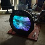
Success, tentatively!
 I let the multiple coats of corona dope on the arc location dry overnight, installed the insulating board in the top of the HV box, and put a rope of high-voltage putty around the flyback coil:   In the picture of the insulator, wires are visible under each end of the board. It is a copper-clad board on one side, so I soldered those wires on to ground the board under nearby screws; they will also hold the board in case the adhesive holding it fails. In the flyback picture, the arc location is at the "3 o'clock" position, to the right in the picture. That was all the putty I had, or I would have used more. I plan to replace it with silicone permanently in any case. Before I applied any power, I did a run-through of the whole process of possible actions and adjustments, and I found that my horizontal linearity coil (also called horizontal tuning, and horizontal efficiency in later sets) was frozen. I had to remove it and apply heat from a heat gun, but it freed up nicely. (Thanks to Tom, Electronic M, for that tip from his own CTC-4 coil, in another discussion I found.) With the coil reinstalled, I put my Simpson 260 inline with the H output tube's cathode, put my HV meter on the anode wire to the test jig, connected the Variac, and increased the voltage in moderate steps. At 80-90 volts, the set slowly came to life, and I watched the HV go to 20kV without any problems. The H output current was low, perhaps 120mA on the meter even with the Variac at perhaps 95-100V, and I did a brief adjustment of the H linearity coil without seeing a big change. At this point, the set had been on for 4-5 minutes, so I shut it down to check the flyback temperature. It was totally cool on the perimeter of the HV coil, including at the arc location, with a bit of warmth in the "spoke" area of the "tire". I think I will replace the Simpson 260 with a new meter (still keeping the 0.1uF capacitor across the test leads) and try another test, also maybe running the AC voltage a bit higher, before saying the test was good and preparing to coat the flyback coil with silicone. One question I have: Should the HV adjustment control give me a linear range of voltage, even with the AC input low, or does the HV regulator circuit function more as a limiter above a certain voltage? Are there any dangers to setting it too low while testing its function, if in fact I can? The HV got to 22-23kV already even with the AC input at perhaps 100V or less. I appreciate any advice here.
__________________
Chris Quote from another forum: "(Antique TV collecting) always seemed to me to be a fringe hobby that only weirdos did."
|
|
#53
01-19-2016, 09:40 PM
|
||||
|
||||
|
Glad my CTC-4 thread helped....Makes me think I should get back to that set.
The regulator is a top end limiter, but IIRC it is referenced to boost or a similar fly derived source so it will dip with line voltage somewhat. There is not a lot of problems with the reg being low (for testing), but that has some dependencies.....If the set wants to produce 40kV with the reg cap off and the reg is dropping it to say 10-17kV the reg load on the fly may heat it up and be detrimental over moderate to extended run times... If it's on for under 10 minutes it probably will be okay. I adjusted my oscillator to perfection with a scope before installing the H output tube, and the adjustments necessary with that tube in, like linearity current dipping, I tried to be totally ready for prior to switch on and perform as soon as it seemed to settle from initial warm up....Perhaps I was over cautious but I never did any harm or had any troubles with the horizontal/HV system in doing it that way.
__________________
Tom C. Zenith: The quality stays in EVEN after the name falls off! What I want. --> http://www.videokarma.org/showpost.p...62&postcount=4
|
|
#54
01-19-2016, 10:27 PM
|
|||
|
|||
|
Chris,
Just a question purely of side interest: Do you notice any difference in the 260's current reading with and without the .1 cap across it?
|
|
#56
01-20-2016, 12:07 AM
|
|||
|
|||
|
I always used a 260 for K current and never thought of putting a cap across it, since it's functionally a dead shunt. Be interesting to see if there's any difference with/without the cap.
Last edited by old_coot88; 01-20-2016 at 12:10 AM.
|
|
#57
01-20-2016, 02:11 AM
|
||||
|
||||
|
Tom, thanks for the notes about the horizontal circuits. I would never have thought to adjust the waveform with the H output not installed, I guess I am too much of a "by the book" person normally.
Old Coot, I used the capacitor because (again) "the books" typically say to do that. The official CTC-4 procedure does not even address the H output cathode current, but rather the screen grid and/or damper current. I will try another test with and without the capacitor and let you know if I see a difference. My other test will be with a DMM, and maybe those are the meters that need such a capacitor across them. (That test will be because I am not 100% sure of my 260's performance.)
__________________
Chris Quote from another forum: "(Antique TV collecting) always seemed to me to be a fringe hobby that only weirdos did."
|
|
#58
01-20-2016, 03:10 AM
|
||||
|
||||
|
Nick and others with better technical background than I have; please chime in here and discuss "CRT LOAD"
I looked up the 2nd anode load for a 21AXP22. It said 500 microamps per gun maximum or 1.5ma total 2nd anode load. (I am assuming full brightness). At 25KV that converts to 37.5 watts (if I did my math correctly 25,000v x .0015A = 37.5 watts) That is certainly enough to warm up the flyback, but I would think the CTC4flyback might be able to dissipate that much heat safely. It is my impression, from discussions concerning blooming under heavy video demand in bright scenes, that a very heavy demand is placed on the flyback during these situations. 21CT55 uses a modified ct100 chassis and the horizontal drive section of the CTC2B chassis is woefully inadequate to provide enough current to the flyback during these bright situations. As a result you can get picture blooming and fade out on the crt. That leads me to believe that CRT places a high demand for 2nd anode current during these bright situations. Therefore can I assume because Chris is using a small crt test jig, that we are never going to see real world demand on this HOT until he hooks up the 21AX and it's associated deflection yoke? The point I am getting at is this; 120ma of cathode current is no where near the kind of load that will be drawn by the cathode of the horizontal output tube during actual use with the 21AX. Therefore any cathode current readings or temperature of the windings need to be done under full load conditions. When full current is demanded during bright scenes on a 21AX with 22Kv or better, then and only then will we be able to determine if the flyback is going to over heat. And I think from dead cold to full temp under normal loading conditions will probably take at least 30 minutes to achieve. It is also my gut feeling that because current and voltage are inverse to each other, that a low voltage at the 2nd anode, will cause a rise in current. It is the rise in current that will causes the flyback to heat up. Think of an arc welder. More current (amps)=more heat. The thing that causes a wire to heat up is the current being drawn through it. Seems pretty basic to me. But I would guess there may be other factors involved. As for the 6BK4, that sucker (essentially a high voltage triode) is designed to limit the upper end of the voltage range by shunting the 2nd anode when the voltage gets to high. So that leads to the next issue. If you have a flyback that is producing (for example) a consistent 30KV and the 6BK4 is set to start regulating at 25KV, isn't the 6BK4 placing unnecessary continuous load on the flyback? Wouldn't you be better off bringing down the output voltage of the flyback so the 6BK4 wasn't loading the flyback output. Sort of like putting your foot on the accelerator of your car and regulating your speed by applying the brakes. You would be better off to ease back on the accelerator instead. Perhaps Chris' flyback wax melted because it was being driven harder than it needed to be, and the shunt regulator was constantly sucking up the excess and loading the flyback when it produced too much HV. These are just my gut feelings (and rambling thoughts about a subject I would like to understand better), and to those members that understand this stuff better than I do, please chime in and lets have some good discussion on the cause and effect of real world current demand on the flyback from a crt that is being driven hard, and the effect of the 6BK4 on a flyback that is producing higher voltage than is required. The better we understand the causes and effects that damage our flybacks (mostly pure unobtanium) the better we can protect these irreplaceable components. Inquiring minds need to know AS an aside comment; I have a CTC4 chassis that I am working with for the Cheltenham. I turned the chassis over and what did I find? I found the HV doorknob cap with most of it's potting wax compound melted out of the housing. Obviously, the doorknob is leaky and producing a lot of heat as it draws current. This is just another place where unnecessary LOAD is being placed upon the flyback. After the ctc4 series these HV doorknobs were eliminated. I imagine the doorknobs were problematic. My 21CT55 had a bad doorknob and it wiped out the flyback. The doorknob should not have any DC leakage. It's job is to smooth the ripple on the 2nd anode. On the CTC5 series, all that was used was the conductive dag coating on the exterior of the plastic crt shroud which acted as a filter capacitor between the metal bell of the 21AX and ground. When the 21CY glass tube came out, dag coating on the tube became the filter cap. So if you have a CTC4 or a 21CT55, make sure your doorknobs are not leaky. I would think it can be a source of excess load on your flyback.
__________________
Vacuum tubes are used in Wisconsin to help heat your house. New Web Site under developement ME http://AntiqueTvGuy.com
|
|
#59
01-20-2016, 06:58 AM
|
||||
|
||||
|
Quote:
500ua per gun is probably a bit overly optimistic; not that the tube couldn't handle it as it certainly would be bright with that much available current, just that I seriously doubt any flyback ever made for an early color TV could produce it. My Director gets pretty close, it has the strongest horizontal section of all my sets and a bright picture even on a so-so CRT. That doesn't mean the flyback necessarily has to get hot in the process though, if everything is tuned the way it should be it's a pretty efficient magnetic coupling device. The horizontal output tube has to bear the full load of anything downstream of it, so that means yoke, HV, other circuits like AGC and gating pulses, AND the rectifier filaments. If the yoke has leakage or some other problem for example you might not necessarily see it on the screen, but it's a load on the horizontal circuit nonetheless. Same goes for HV leakage paths to ground and surrounding circuits, dusty/dirty HV cages and old HV wiring all contribute to losses. These are all reasons why each restoration I do begins in the HV cage and horizontal circuit. Quote:
Same processing circuits, much different HV setup with better flyback and larger horizontal output tube. They made a compromise when they designed each set, though if you ask me they made a mistake with the CTC-5 not a compromise. Quote:
 Quote:
FWIW, most early color TV's don't make enough HV to be dangerous. I run my Wingate with the 6BK4 disconnected all the time, because even then it struggles to make 22kv on a good day with a tailwind. I wouldn't try it with anything earlier though, the first ones were absolutely lethal with HV production. Whatever you do, do not allow anode voltage to rise past the upper limit of what the CRT can handle.
__________________
Evolution... 
|
|
#60
01-20-2016, 11:35 AM
|
|||
|
|||
|
Think of the CRT and the shunt regulator as two variable loads on the flyback. When the CRT has a bright scene, it becomes a greater load while the shunt regulator becomes a lessor load. Conversely, a dark scene causes the CRT to become a lessor load while the shunt regulator becomes a greater load. The whole idea here is to present a more or less constant load on the flyback and the circuitry upstream of it. The real question is whether the designers specified the flyback so that it can withstand this combined load (CRT plus shunt regulator) on a continuous basis without having too much of a temperature rise.
I always liked the Zenith pulse regulator although it wasn't as well regulated as a shunt regulator. I never had to replace a Zenith flyback with a pulse HV regulator.
|
| Audiokarma |
 |
| Thread Tools | |
| Display Modes | |
|
|


 Linear Mode

