
|
|
|
#16
 02-10-2012, 07:42 AM
|
||||
|
||||
|
Well, I finally came across a Hoffman 706 with a non-functioning solar array.
This one is a TP706, and although it looks good, it's a basket case. First off, the speaker cone is water damaged. The radio doesn't appear to have been in a flood, so my guess is it was probably left under a sprinkler at some point in its life. Second, the solar array didn't have any output. This is one of the early 706's with the rectangular solar chips that are soldered together in an overlapping fashion like shingles. I cut the adhesive away from the bottom panel to remove it and found that the foam that held the array against the top of its enclosure had completely deteriorated to mush, allowing the array to move around and break into 4 pieces. The other issue can be seen if you look closely at the area where the negative wire is taped to the back of the array. Apparently the adhesive of the tape, in conjunction with the deteriorating foam, caused the insulation of the wire to completely break down. The wire is shorted to the back of panel. This solar array is extremely fragile! It's going to be a challenge to solder it back together! 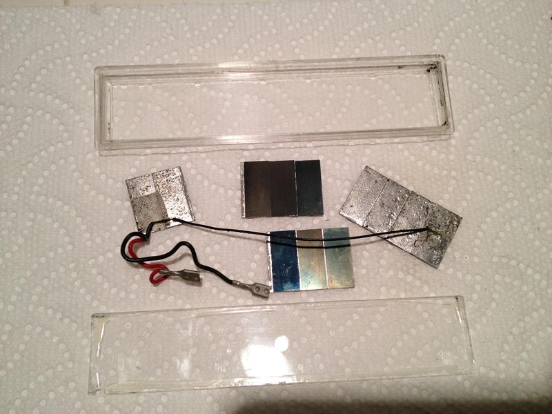

|
|
#17
02-10-2012, 08:18 AM
|
||||
|
||||
|
Solar pan
Looks like a project.
When I soldered my panel pieces back togeather I turned down my soldering heat Temperature. What I wished I had was some silver solder. Something that would melt at a lower temp. I noticed that the panel material has a real low melting point, so be careful. My spongy stuff was in bad shape too. I couldn't find anything to replace it with. What were you going to use to replace the sponge with? Good luck Buzz 
__________________
______________________ Buzzsaaw Sunlitedreams.com
|
|
#18
02-10-2012, 10:12 AM
|
||||
|
||||
|
I may try to use some of that low-temp (430 F) solder paste that comes in a syringe. I'll be careful though since I'm not sure how it will react with the original solder and silicon.
For the foam, I know I have something at home or at the office that will work. I'll just have to make sure that it's not the anti-stat variety!
|
|
#19
02-10-2012, 10:35 AM
|
||||
|
||||
|
Make sure it's not Conductive.. yes.. that would be anti-static.
Some anti-static bags have a Detergent coating that conducts the static around to the other side or equalizes it. I don't know about bug (for IC's) foam or sponge. Buzz
__________________
______________________ Buzzsaaw Sunlitedreams.com
|
|
#20
02-10-2012, 07:39 PM
|
||||
|
||||
|
Success! Got the array put back together. It puts out about 12ma under the light of a 60 watt bulb. That's as good as gold for one of these early solar arrays.
The solder used on this array was not low-temp by any stretch of the imagination. My little Hakko iron would not generate enough heat to melt the solder to sweat the joints back together. It was like trying to melt aluminum. I ended up using a Weller micro-torch. Worked great and it didn't damage anything. While I was at it, I touched up all the joints, since quite a few of them exhibited some flex. Afterwards the whole thing was good and solid, and flat. I could not find the correct thickness of black foam for the backing, so my wife Janet took a 1/2" thick piece of extremely soft small-celled black foam and cut it down to 1/8" thickness with a wide blade X-Acto knife (she ALWAYS helps during a restoration, whether it's a radio, TV, tape-deck, old truck or motorcycle). I put the back on and sealed it with GC Vinylite cement, which appears to be the same stuff Hoffman used to close it up. Now on to the radio and speaker..... 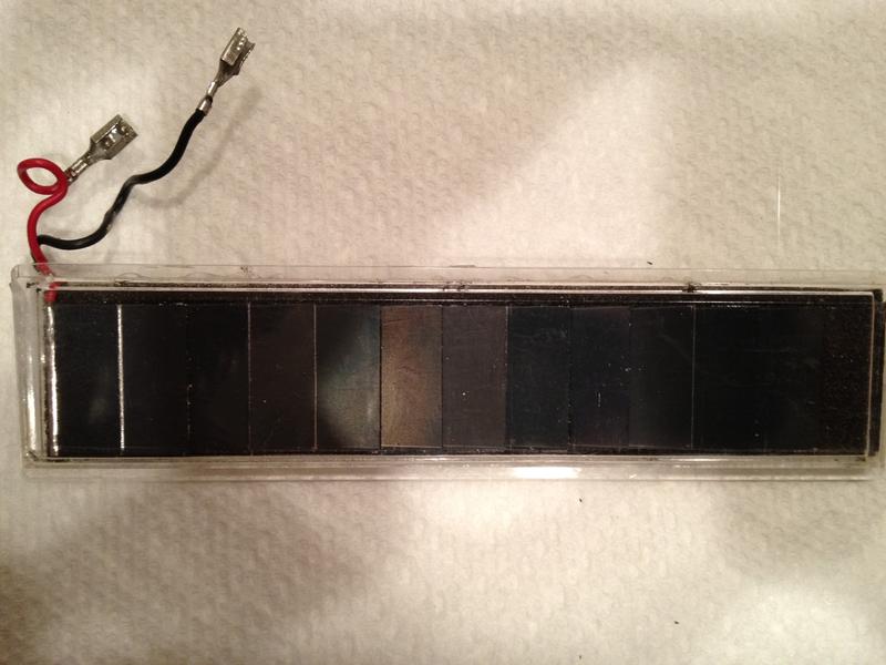
|
| Audiokarma |
|
#21
02-10-2012, 08:08 PM
|
||||
|
||||
|
Wow..
That's great! Looks brand new! It's neat that da Spouse helps out too.! Next ... she'll be buying old radios for herself to restore.. Then she'll become a ham. Say good buy to your nice shop area. heehee! Buzz
__________________
______________________ Buzzsaaw Sunlitedreams.com
|
|
#22
02-10-2012, 08:48 PM
|
||||
|
||||
|
I forgot to mention that I did tack solder some new electrolytics into this one just to find out how close it is to working. It seems to show signs of low sensitivity like you mentioned. After I install the caps permanently, I'm going to hook it up to the signal generator and scope to do a side-by-side comparison with one of my other 706's to try to determine the cause. It may need some tweaking, but it didn't look like anyone had been inside this one. Hopefully it's not a tin whisker problem in one of the transistors.
One thing I did notice though is that the loop stick antenna in this one is different than my other 706's. The windings on the ferrite bar go from one end to the other. There is just barely enough room for the 2 little metal clips that hold the bar to the circuit board. My other 706's have windings that use just 3/4 of the bar length. I'll post my findings when I get there.
|
|
#23
02-16-2012, 10:41 PM
|
||||
|
||||
|
The PC board is different too. Looks a lot older and doesn't even come close to what's shown in the Sam's.
I worked on it for awhile, then my signal generator quit. Transformer! Crap! Bought a new "modern" one on eBay. Should be here tomorrow. But what I've found so far is that this ain't gonna be easy!
|
|
#24
02-17-2012, 10:38 PM
|
||||
|
||||
|
The 2N253 1st IF transistor is bad in my TP706. As I mentioned earlier, the set plays, but suffers from low sensitivity and volume.
BTW, the transistor date codes are all 830 or 831. That equates to the 30th and 31st week of 1958. Not sure what I'm going to replace it with yet. Last edited by Smoky Pond; 02-17-2012 at 10:56 PM.
|
 |
|
|


 Linear Mode

