
|
|
|
#1
 03-19-2012, 10:03 AM
|
||||
|
||||
|
Hi,
I need a schematic for the Admiral 24 A 125 N (10" console) since 21 years.  I found out, that it is the 20 A 1 chassis version, according the Riders information.  My set has a seperate chassis for power supply and output in the speaker compartment. In the past I got wrong schematics with the power transformer on main chassis offered. I need a clean scan from Sams including the power transformer datas to rewind for 230 volts/50 Hz use.  Thanks in advance, TV-Collector 
|
|
#2
03-19-2012, 10:58 AM
|
||||
|
||||
|
That's going to be tricky, I'd say, because the vertical oscillator is based on 60Hz line frequency, and with 50Hz, you might have trouble trying to get it to sync, even if you make the oscillator run at the correct speed. It might not lock in, since it may need to reference the 60Hz A/C. I defer to any engineers on that, though.
Charles
__________________
Collecting & restoring TVs in Los Angeles since age 10
|
|
#3
03-19-2012, 12:02 PM
|
||||
|
||||
|
You can download the Riders service info here: http://www.earlytelevision.org/tv_sc..._diagrams.html
I would think it'd be easier to replace the transformer with a 230v 50 Hz one or maybe use an external power converter if such a thing exists ? It uses a blocking oscillator for the vertical which I believe runs independent of the AC line frequency.
|
|
#4
03-19-2012, 01:03 PM
|
|||
|
|||
|
That set has two power transformers. One for the audio output and one for the TV chassis.
|
|
#5
03-19-2012, 02:11 PM
|
||||
|
||||
|
Some models do, but not the 23A12N with 20A1 chassis. One power transformer, two chokes and an audio output transformer.
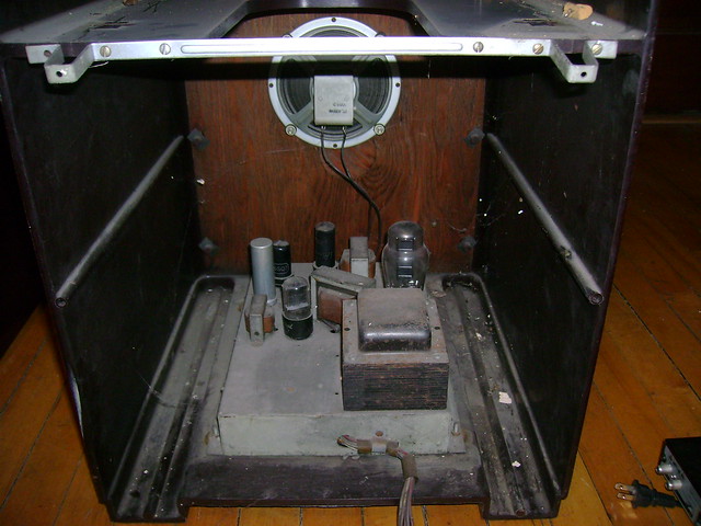 Here's a 30A1 lower chassis with dual transformers. 
|
| Audiokarma |
|
#6
03-19-2012, 03:40 PM
|
||||
|
||||
|
Here is a possibly stupid, cheap, and noisy idea......If you can find a generator motor that puts out 60Hz, 120V with sufficient current and connect it to the powercord of the set, then connect the shaft of this generator motor to the shaft of a regular motor that runs off European mains with the right mechanical output specs, then you could make something of a crude dynamotor supply for the set and keep the original power transformer in place.
__________________
Tom C. Zenith: The quality stays in EVEN after the name falls off! What I want. --> http://www.videokarma.org/showpost.p...62&postcount=4
|
|
#7
03-19-2012, 04:02 PM
|
||||
|
||||
|
Or how about a 12 VDC power inverter ? http://www.sears.com/search=cobra%20...12%20volt%20dc
Not as much fun as Electronic Ms suggestion of course 
|
|
#8
03-19-2012, 07:59 PM
|
||||
|
||||
|
Thought comes to mind: if you have a second 120V power transformer of similar power rating, and a high current heater secondary of the same voltage as the transformer inside the TV set. connect the two primaries in series, and with 220V power applied to this series circuit, connect one side of both the heater windings of both transformners together, and measure the voltage between the other ends of both windings. If you see something less than say 2V for 6.3V windings, you should be able to connect them together, to make both transformers evenly distribute half the 220VAC between them. If you get 12VAC, swap the first heater connection on one of the windings, then check that you get less than around 2V. The heater load should evenly split between the two transformers, and some of the power for the B+ would flow between the two heater secondaries, and also between the two primaries.
Haven't tried it, so YMMV...
__________________

|
|
#9
03-20-2012, 09:56 AM
|
||||
|
||||
 Thanks for the input. Thanks for the input.If the sinc-section needs another construction I will do it with parts of german junkers. I had no problems with the 7-Motorolas and the GE-train.  My GE-train is converted and sweeped to CCIR european standard and works fine with it.  The german Funkschau printed an nice article in the late 50s how a TV repair man converted US-TV-sets from the troups to CCIR standard, so that the troops can watch german television. He wrote that he take care about it to make it easy to convert them back, so that they have no problems with the sets when they return to the USA. He wrote that the old roundies are better in quality and picture sharpness than the modern rectangular sets. Several hundreds of sets he converted. I have a few 110 Volts power transformers and 2 adjusting transformers for any AC voltage. But just the 60 Hz operation makes a rewinding of transformers importent. A friend from Berlin rewinded a lot of power transformers for me, a part of them were burned. He was the right hand of the boss of a transformer & electro motor rebuilding company. With the Admiral transformer we (he) have a little problem (he is elderly - both Because of the black color I will visit another guy with a strong supersonic tub, this will help. I think my 24 A 125 N has the same chassis like in the bakelite console, only one power transformer. It is crated and hidden behind many other TV sets Best regards, TV-Collector
|
|
#10
03-20-2012, 02:20 PM
|
||||
|
||||
|
Quote:
__________________
|
| Audiokarma |
|
#11
03-20-2012, 05:09 PM
|
|||
|
|||
|
The chassis with one power transformer has two HV winding. One is like 275 and the other 155vdc. A real pain to find a replacement for. Stancor made a replacement for it (P-8160) Mine was shorted but did find a the replacement.
Terry
|
|
#12
03-22-2012, 06:49 AM
|
||||
|
||||
|
@WA2ISE
Yes. this is an interesting post, just because the repair man thought, that this has something to do with saving another IF-stage. With smaller bandwidth a higher amplification allows to receive stations from far away. He wrote, that americans prefer indoor antennas instead of outside constructions on the roof to watch television. Thanks, TV-collector
|
 |
|
|


 Linear Mode

