
|
|
|
#16
 02-01-2017, 08:19 PM
|
||||
|
||||
|
Quote:
__________________
John 
|
|
#18
02-17-2017, 06:10 PM
|
||||
|
||||
|
Thanks, that looks pretty simple. What type of transistor did you use?
Regards, Phil Nelson
|
|
#19
03-09-2017, 09:49 PM
|
||||
|
||||
|
Out of curiosity, I built that preamp/inverter on a piece of perfboard, using a 12V battery supply and a 2N3903 transistor:
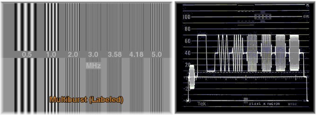
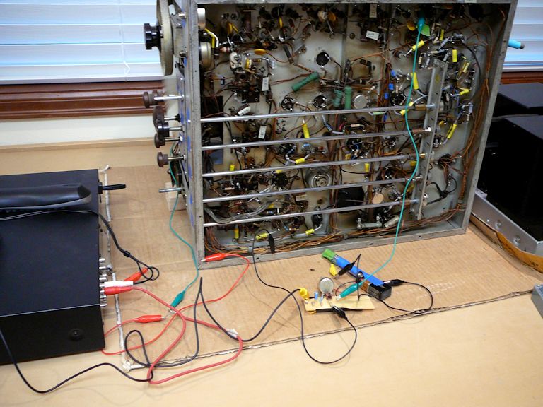 It works, after a fashion, but it isn't great. The first pic shows the video signal (color bars) direct from the pattern generator: 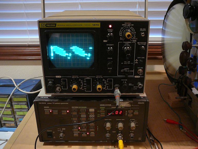 And below is the signal coming out of the preamp. The pattern is inverted, but kinda "slenderized," and there seems to be some noise or instability: 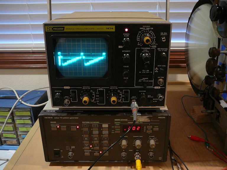 The screen image is disappointing. It has decent contrast and detail, and the pot on the collector acts as a contrast control, but the vertical is quite unstable and retrace lines are visible nearly all of the time (not much in this pic, though): 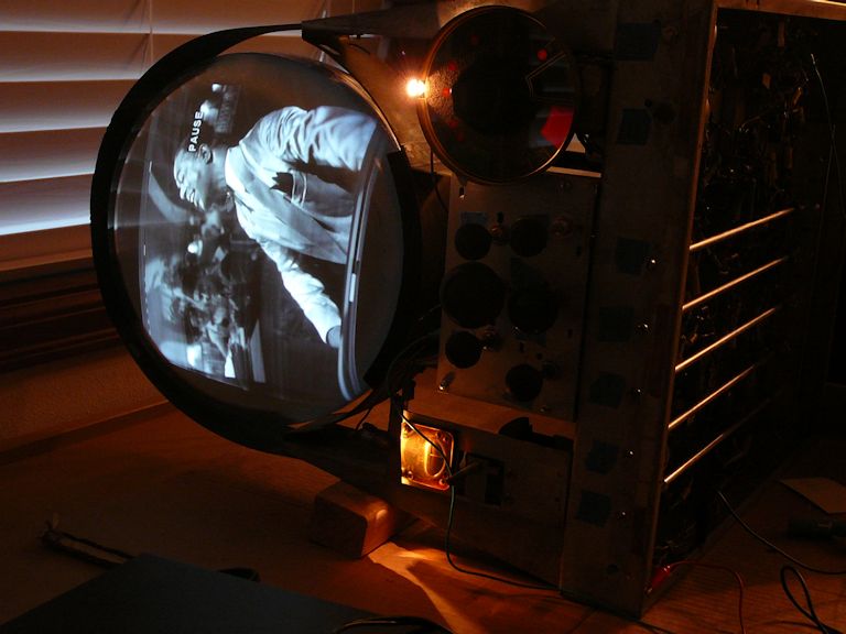 I wonder if the 2N3903 transistor wasn't the best choice? The local supplier didn't have much to pick from. Here's the 2N3903 data sheet: http://www.brown.edu/Departments/Eng...s/2N3903-D.pdf Phil Nelson Phil's Old Radios http://antiqueradio.org/index.html Last edited by Phil Nelson; 03-09-2017 at 10:05 PM.
|
|
#20
03-09-2017, 10:57 PM
|
||||
|
||||
|
Looks like lack of bandwidth if you ask me, did you sweep it to make sure it's passing all frequencies up to about 4.2mhz? Probably could use some peaking.
__________________
Evolution... 
|
| Audiokarma |
|
#21
03-09-2017, 11:05 PM
|
|||
|
|||
|
I wonder if the transistor is too "slow". You might need a true video amp transistor.
|
|
#22
03-09-2017, 11:07 PM
|
|||
|
|||
|
You beat it to the post miniman82...LOL
|
|
#23
03-10-2017, 01:17 AM
|
||||
|
||||
|
Quote:
Quote:
Thanks, Phil Nelson
|
|
#24
03-10-2017, 01:57 AM
|
|||
|
|||
|
I would modify it slightly so you're gain-controlling it from the input side.
|
|
#27
03-10-2017, 02:13 PM
|
||||
|
||||
|
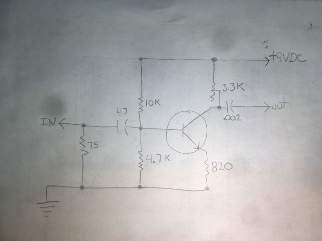
The 4.7 is 4.7 microfarads, right?
The + side should be connected to the transistor base, but the way you have it drawn, the negative side is connected to the base. Which way do you really have it? That transistor should be OK for video frequencies (Ft is 250 MHz, which means the internal capacitances reduce the gain to unity at 250 MHz). Are you using a 10x probe on the scope? A 1x probe may add too much stray capacitance and reduce the high frequency response. You can detect this by watching the picture while you apply and remove the probe.
|
|
#28
03-10-2017, 02:26 PM
|
||||
|
||||
|
You are going into pin 4 (grid) of V4 (6AC7), right?
Did you disconnect the detector diode? Also, .002 microfarad is too small to drive 5.6k. The low frequency cutoff will be about 14 kHz, causing vertical sync problems. Since 5.6 k is close to your collector load, it will reduce the AC gain, so disconnect it and replace it with something like 56k. This will lower the cutoff to 1.4 kHz, still too high. Then, to get the low frequency response down to 30 Hz, the coupling cap has to be increased to 0.002x1400/30 = 0.09 (use 0.1 microfarad). Last edited by old_tv_nut; 03-10-2017 at 02:39 PM.
|
|
#29
03-10-2017, 02:33 PM
|
||||
|
||||
|
Once you have made the changes, your waveform should look much better. Then, if the chroma (or high frequency multiburst) amplitude is a bit low, we can talk about adding some peaking.
|
|
#30
03-10-2017, 03:04 PM
|
||||
|
||||
|
By the way, if you don't like replacing the 5.6k ohm resistor, you could add an emitter follower to your amplifier to drive the lower impedance - but you would also have to increase the coupling cap from 0.1 uf to 1 uf, a nuisance because you are getting back into the range of polarized caps.
|
| Audiokarma |
 |
|
|


 Linear Mode

