
|
|
|
#1
 05-28-2011, 03:51 PM
|
|||
|
|||
|
Rectifier Replacement on my Blaupunkt tube radio
My Blaupunkt 40400 Vollestereo console restore
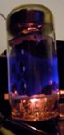
I recapped the unit and changed some resistors I have now read up on rectifiers and think I understand more about them and their application http://en.wikipedia.org/wiki/Diode_bridge http://w3hwj.com/index_files/RBSelenium2.pdf First, about me. I am a neanderthal, mouth breather, barely able to walk upright when it comes to Electrical Radio service. I have never measured a voltage live and mostly just replace capacitors and resistors What I learned: Many electrical devices are powered from AC but actually run on DC, so AC has to be converted to DC. Diodes limit AC to one direction, causing DC. This is called "rectification" Rectified DC power "pulses" from the output cathode, holding back the reverse AC, and surging on the forward AC as AC alternates current. This is called "Ripple". A capacitor can smooth this pulsing out. http://en.wikipedia.org/wiki/Reservoir_capacitor Modern diodes used for rectifiction are more efficient then those of yore and the DC '+' output needs a resistor to drop the voltage back to specification. The voltage is on the schematic. Start with a 100ohm and adjust the ohms up or down till you get the required voltage from the spec. Use a high watt like a 3 or 5 watt resistor My '+' voltage says 300v on the schematic That would be DC volts. Make sure your meter can read that high a voltage A half wave recification is just a single diode and a resistor The full wave rectifier is used so that you can plug in the cord any way and the diodes will sort it out and deliver correct DC to the + and - lines Full wave bridge rectifiers are marked with ~, ~, +, - The ~ are AC inputs and the +/- are DC outputs This radio's original silicon or selenium rectifier was replaced by the 4 diodes making a full wave bridge rectifier circuit. One diode has a broken lead I believe I can replace the broken IN4007 diode and get the recification working I also believe I can replace the whole 4-diode set up with a "NTE5316 R-SI,BRIDGE,800V, 8A" device as rectification I will put a 100ohm 5 watt power resistor on the + side to compensate for the more efficient silicon diodes in the bridge and measure the voltage on the +/-and adjust the resistor to get my 300v The radio already has a 100uf Electrolytic capacitor that the - line goes to. I think that is the ripple smoothing capacitor I THINK THAT SPONGY LOOKING THING IN THE SILICON BEEFUP PICTURE IS A CAPACITOR. There are no markings. It is conncted to the '-' side Questions: Any guess what that spongy capacitor value might be? What would that capacitor do for the '-' side What capacitor should I use to smooth the pulsing? Electrolytic? Value? Voltage? Is that connected between the + and - output lines? Should I incorporate a bleeder resistor? What value? I could not calculate the value from the formula. How would that be included in the circuit? Any input would be helpful, especially the "Don't do that, you'll kill yourself" kind Last edited by omegaman; 05-30-2011 at 02:28 PM. 
|
|
#2
05-28-2011, 04:53 PM
|
|||
|
|||
|
More rectifier questions
This is a perfect "ID ten T" error
I now believe that the tubes and sockets I talk about in this post have nothing to do with rectificaiton and are superflous to the discussion of my rectification thread. NO THEY SURE DONT Hi! This Omegaman from the future and I just wanted to say that those sockets are for the speakers. Had I only LOOKED at the perfect example of MY working unit (it is tucked away right now) I would have realized that these were the speaker outputs plain and simple. The tube stuffed in one socket really threw me. Case closed! but... The unit I am working on is a different receiver than the one posted in the original console portrait (The whole console picture). The unit pictured is my German version of the 40400. It works great and I recapped that awhile ago. (My first recap) The FM on it only goes to 100 which limits it so... I bought this American version of the same radio as a parts unit, no console, maybe as a replacement for the German one. The American version is not as beautiful as the German one. The Glass plate The American one is actually in better condition so I decided to restore it And on to the questions... The German unit does not have tubes in the pictured (below) lower right part near the output transformers. This American unit has one EABC80 tube in marked socket 'I'. What would a EABC80 tube be used for in this application? My wild guess is for the expanded FM beyond 100, except it is nowhere near the tuner? Why is 'II' (the right socket) empty? Could this EABC80 tube be mistakenly placed in this socket? YES! On my German version there are no tubes in these sockets. I thouight the sockets were for testing or something NOPE SPEAKERS Could these tube sockets be for tube rectification? Which have been replaced by the SS rectifier. NOPE SPEAKERS Any advice on this subject would be very helpful LOOK AT THE PICTURES YOU TOOK IN THE FOLDER( NOT HERE) The American 40400 Unexpected tubes No Tubes in the schematic or literature Last edited by omegaman; 06-02-2011 at 07:04 PM. Reason: more details
|
|
#3
05-28-2011, 06:06 PM
|
||||
|
||||
|
All I can suggest is perhaps that's a multiplex adapter?
That's a very nice set  I'm sure someone will be able to offer some better advice. I'm sure someone will be able to offer some better advice.
|
|
#4
05-28-2011, 06:15 PM
|
|||
|
|||
|
Quote:
I am trying to find the sockets in the schematics, but schematics are in German unt meine Deutsch ist nicht sehr gutten I am leaning towards thinking that the EABC80 does not belong there
|
|
#5
05-28-2011, 07:38 PM
|
||||
|
||||
|
One of my friends is German, and a retired Electronics Technician. Can you post the sections you are trying to get translated? He'd do a great job...
Cheers,
__________________
Brian USN RET (Avionics / Cal) CET- Consumer Repair and Avionics ('88) "Capacitor Cosmetologist since '79" When fuses go to work, they quit!
|
| Audiokarma |
|
#8
06-02-2011, 07:09 PM
|
|||
|
|||
|
Yes the sockets were for the speakers
And I got my rectification issues sorted out Rectification is a important part of electronic restoration. It's important to learn about it Always research any subject
|
|
#9
06-02-2011, 08:26 PM
|
||||
|
||||
|
Somewhere in my stash of transformers, I have an Output Transformer for either a Grundig or Telefunken unit that is similar to your Blaupunkt. We tried finding a replacement for a bad transformer here in the states to no avail, but a phone call to the AAFEEs TV repair guy in Germany got us one in the mail - this was in 1984! I still have the October 27, 1984 International Herald Tribune that was used to wrap the new transformer for packing. Interesting snapshot of history - George Schultz was the Secretary of State, Mondale was running for prez, and the Pope's would-be-assassin was in the news as well. We never did get to fix the unit - the guy lost interest in getting it fixed.
Interestingly enough, a guy at church keeps offering me one of the console Grundigs from the 1960s. It works fine, but I can't get him to name a price, and I don't want to lowball him and p*ss him off. He knows I'm interested, though. Really nice codger - in his 80's and still active! Really nice resto job on your Blau! You should be proud!  Cheers,
__________________
Brian USN RET (Avionics / Cal) CET- Consumer Repair and Avionics ('88) "Capacitor Cosmetologist since '79" When fuses go to work, they quit!
|
|
#10
06-11-2011, 06:42 PM
|
|||
|
|||
|
I power the Blaupunkt up after the rebuild
I completed all the changes I wanted to do on the Blaupunkt and had my first plugs out power up test. I got lucky and it came up nice and sweet. Wow the EM84 works. FM Tuner is very accurate. Lots of stations across the band. AM I think needs new tubes as it doesnt seem as good but it does work
I made a DIN to RCA cable to plug in a real stereo source (radio is pre MPX) no adapter interface either This was my second time doing the exact same radio chassis so it was familiar ground but this project was more extensive and thorough five filter caps 14 e-caps 6 x .022 caps 4 x .047 caps 4 resistors New full wave bridge recitfier QD the tuner D5 the controls I learned alot about rectification from the internet and it is not so foreign to me any more I measured the rectified DC output at 308vdc. It was predicted that the modern rectifier would be more efficient and the output voltage would be 5-10volts higher, requiring a high watt resistor to bring the vdc to 300 I put a 150ohm 5 watt resistor on the + from the rectifier and measured the voltage at 280 vdc. The schematic says 300 so I have to pull the 150 and try something like 60ohm, if linear. I'll get an assortment of resistors to get it right at 300vdc One thing I paid more attention to on this project was the mechanical connection in the solder joints. I made an extra effort to really wrap the wire connections together. I dont want to say that I ever relied on solder alone to hold a connection. Since it passed its first trial run I am going to mount it into the console and listen to it proper ya know.. if anyone is interested Last edited by omegaman; 06-11-2011 at 06:58 PM.
|
| Audiokarma |
 |
|
|


 Linear Mode

