
|
|
|
#196
 02-06-2013, 11:17 PM
|
|||
|
|||
|
while checking on brightness level I checked the cathode and grid voltages at the CRT. I don't have my VTVM handy, but the green grid was maxed out at 240v while the schematic has it a 255, the cathode voltages were much closer.
I don't know if the load of the DMM is more than a VTVM, but I may just check that 1 meg resistor that feeds the B+ to bias the grid thru the background pots. I would think that I should be able to hit the 255 at something less than max setting, as opposed to the max of 240v. the other drive controls seem to have no problem getting the the correct bias setting. While I am able to get good gray scale, its at a reduced brightness. Later I plan to install my CRT test socket so I can see where the G2 voltages are (they are not easy to get at like the cathode and G1). I am pretty sure I should get a brighter pic, the CRT test fine, and the HV is solid at 22.5 kv, I know the early CRTs were not as bright as later but I would at least like to see how it looks when the voltages are closer to what is in the schematic. 
|
|
#197
02-07-2013, 05:00 PM
|
|||
|
|||
|
chasing low brightness down the CRT bias voltages turned up some interesting notes. The blue background when maxed out would only bring up the G1 to 240v the schematic calls for 255v and it makes a big difference here. So I started by checking the resistance of the 1 meg resistors that couple the pot adjusted boost voltage to the G1s. I checked the blue G1 1 meg out the circuit and it tested at 6 megs. Replaced that one. The other two G1s had no problem getting two the specified voltage so I will leave them be for now (can't test in circuit and I don't want to replace something that is working, even if it has drifted as the pots can make up the difference).
While I was at it I check the 10k resistor that provides the boost to the pots, it was 16k. I have noticed that when it comes to voltage dividers you need to be pretty close to the correct values to have the correct ratios to divide the voltage by. Since I was low on G1 voltage and a drifted high resistor would make that worse I went ahead and replaced it as well.
|
|
#198
02-07-2013, 08:31 PM
|
|||
|
|||
|
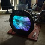
turned it on and wow, solid blue screen, I was able to turn the background control to about the 1/2 way, and now since I was not limited to brighness (and greyscale to the weakest color blue) I was able to increase the overall brightness to what is pretty much normal for all my color sets.
I am getting a bit tired so will leave the checking of the screen voltages to later, but one of those (or both) resistors was really a problem (the 10k that was 16k or the 1 meg that was 6 meg). Still no blooming at all, I don't know why you guys with 5's are having such low HV voltage and regulation issues, this one seems rock solid. All I did was make sure I had good HV tubes and I did change out the 83k to 120k plate load resistor on the horz board, but that was just to get the fly current as low as possilbe with out a drive bar (there is just a hint of one in there now, 100k would prob be perfect). Iam getting a solid 22kv with plenty of head room. My recommendation to folks having low brightness, remember to check voltages at the CRT.
|
|
#199
02-07-2013, 09:32 PM
|
||||
|
||||
|
I don't know if mine has the mods done to it or not, and I'm 950 miles away from being able to find out any time soon. But as I said, yours must be the exception rather than the rule. Every single one I've run into so far has been really weak, even with pots for HV and drive mine fails miserably to sustain 22kv at anything close to a normal viewing brightness level. Count your lucky stars.
__________________
Evolution... 
|
|
#200
02-07-2013, 10:55 PM
|
||||
|
||||
|
I am currently hundreds of miles away as well from working on my set. But I have exactly the same problems with my CTC5 as Nick. The shunt regulator is hardly passing any current because my set is only generating about 22kV with the shunt removed.
I am curious if in the murky past someone hasn't replaced the Horizontal Output Transformer in your set. Are there any traces of resoldering?
|
| Audiokarma |
|
#201
02-07-2013, 11:23 PM
|
||||
|
||||
|
Quote:

__________________
Charlie Trahan He who dies with the most toys still dies.
|
|
#202
02-08-2013, 08:04 AM
|
|||
|
|||
|
the fly looks very orig, I can see no evidence of replacement, I am basing this on how it looks compared to two other CTC-5 chassis that I have (and have not done anything with so don't know how they will perform) it has a kinkda grey/green moldy looking tire. Just for the grins I am going to check the B+ under load and see what I am getting. Could not see any difference in solder of the Fly connections either.
Last edited by DaveWM; 02-08-2013 at 10:40 AM.
|
|
#205
02-08-2013, 02:03 PM
|
||||
|
||||
|
No wonder you're making more HV, you're putting in too much power at the AC side. Turn down the power to 117 VAC, then tell me how much HV you end up making... You'll be struggling just like the rest of us. That also explains why your fly is getting warm, I can run mine for hours on end and it's not even thinking of heating up.
This is why I'm in favor of modifying the chassis for more HV, instead of simply cranking up the power at the plug. There has got to be a way to make these things better, without risking the horizontal output transformer.
__________________
Evolution...
|
| Audiokarma |
|
#206
02-08-2013, 02:38 PM
|
|||
|
|||
|
117 I get 22.5 with the shunt pulled right about 21.5 (my meter is not that fine, but its about 1/2 of a 2.5kv increment) this is with the brightness as below.
will leave it on for a while and see hot hot the fly gets. Last edited by DaveWM; 02-08-2013 at 02:48 PM.
|
|
#207
02-08-2013, 03:49 PM
|
|||
|
|||
|
after about 1 hr I was still at about 160 at the hottest spot, I think I will stay with plan A and put in the forced air cooling and not sweat the line voltage so much. It did not seem to reduce the heat that much.
|
|
#208
02-08-2013, 10:13 PM
|
|||
|
|||
|
just leaning a fan on the back edge of the cage and the yoke, roughly aiming it towards the fly is keeping the temps much lower, I doubt I will hit 125 even with this poor temp arrangement. Yea, a fan is def in order.
|
|
#209
02-08-2013, 11:17 PM
|
||||
|
||||
|
Quote:
__________________
Charlie Trahan He who dies with the most toys still dies.
|
 |
|
|


 Linear Mode

