Videokarma.org

Go Back   Videokarma.org TV - Video - Vintage Television & Radio Forums > Early Color Television

We appreciate your help

in keeping this site going.
Reply
 
Thread Tools Display Modes
  #136  
Old 02-09-2011, 10:22 PM
old_tv_nut's Avatar
old_tv_nut old_tv_nut is offline
See yourself on Color TV!
 
Join Date: Jul 2004
Location: Rancho Sahuarita
Posts: 7,193
Quote:
Originally Posted by rca2000 View Post
So, another way to describe the HOT ckt would be like a "switching power supply", I reckon, and class "C" is not too far off.

As we know, in an SMPS, the switch transistors must be on or off, and nOT much in between..or WAY too much current--and then destruction--immediately follows.
Reply With Quote
  #137  
Old 02-09-2011, 11:07 PM
mbates14 mbates14 is offline
VideoKarma Member
 
Join Date: Apr 2004
Posts: 1,003
oh yea. ive had my fun building DIY SMPS circuits. WEEEEEEE

especially when your not pushing the gates hard enough, you power up your circuit, works for a little bit then... KERRRPLOWWWWWW

weee yea what fun....
Reply With Quote
  #138  
Old 02-10-2011, 05:32 AM
trojanrabbit trojanrabbit is offline
VideoKarma Member
 
Join Date: Apr 2010
Posts: 21
Of course a flyback is a type of switching power supply (having designed a couple).

And sweep tubes were commonly used in lower cost amateur SW transmitters, probably running pretty close to Class C (I think you could get 100W PEP SSB out of a 6JE6). You tuned the final to minimum current.
Reply With Quote
  #139  
Old 02-10-2011, 12:14 PM
Kevin Kuehn's Avatar
Kevin Kuehn Kevin Kuehn is offline
Workin' Late Again
 
Join Date: Jan 2011
Location: WI
Posts: 3,824
Quote:
Originally Posted by old_tv_nut View Post
The HOT under normal operation is either on hard, so the voltage across it is low when current is flowing; or it is completely off, so the current is zero while the voltage is high. Therefore , the power dissipated is low, because the product of (voltage x current) is low or zero. Without the drive waveform, it can be somewhere in between - this condition of having both current and voltage means that the power dissipated in the HOT goes up drastically.
I don't see a problem with installing a bypassed cathode resisitor to limit plate current, in the event of drive signal loss. My mid 50's RCA B&W has this. But a lot of TV's don't have it. Were they too cheap to spring for a resistor and cap? What am I missing?

Kevin

Last edited by Kevin Kuehn; 02-10-2011 at 12:22 PM.
Reply With Quote
  #140  
Old 02-10-2011, 04:19 PM
miniman82's Avatar
miniman82 miniman82 is offline
First Light: 1952-2011
 
Join Date: Jun 2009
Location: Great Mills, MD
Posts: 4,159
Perhaps the added cost was not justified? I read that one resistor was saved in the matrix of the 21CT55, vs the CT-100. You might be surprised the lengths OEMs go to for cost reduction; some of it borders on a safety risk, especially with cars.
__________________
Evolution...
Reply With Quote
Audiokarma
  #141  
Old 02-10-2011, 04:26 PM
John Folsom's Avatar
John Folsom John Folsom is offline
VideoKarma Member
 
Join Date: May 2004
Location: Melbourne Florida
Posts: 932
The resistor elimination in the 21CT55 matrix from the CT100 design was a patent dodge. RCA did not want to pay royalties on I/Q demodulation. Well, thats the story I heard. RCA was known to do almost anything to avoid paying royalties.
__________________
John Folsom
Reply With Quote
  #142  
Old 02-10-2011, 05:17 PM
Pete Deksnis's Avatar
Pete Deksnis Pete Deksnis is offline
15GP22 demo @ ETF 2007
 
Join Date: Jan 2005
Location: Big Rapids, MI
Posts: 761
Quote:
Originally Posted by John Folsom View Post
The resistor elimination in the 21CT55 matrix from the CT100 design was a patent dodge. RCA did not want to pay royalties on I/Q demodulation. Well, thats the story I heard. RCA was known to do almost anything to avoid paying royalties.
John. I came to the same conclusion recently. The quadrature transformers for the CTC2 and CTC2B chassis have different part numbers. They would have to be since the demodulation angle is different for R-Y demodulation than it is for I demodulation,

I do not have a CTC2B chassis to test my theory, but one must rule
out the possibility that the CTC2B chassis does not properly decode the color signal transmitted by an NTSC broadcast transmitter. The two color signals, I and Q, that are trasnmitted by NTSC standards are in quadrature. In the CTC2B the decoded chroma, Q and R-Y, are not. When a quadrature signal is encoded, it must be deconded in quadrature if crosstalk is to be minimized.

If I am right, the CTC2B chassis is inferior to the CTC2 chassis when decoding an NTSC broadcast.

Now, it is always possible that some stone has been left unturned by me. Perhaps eliminating the one insignificant-in-cost resistor in the CTC2B matrix somehow negates the not-in-quadrature problem. I don't know.

BTW: I believe it was probably Philco that RCA was dodging.

Pete

Last edited by Pete Deksnis; 02-15-2011 at 10:51 PM.
Reply With Quote
  #143  
Old 02-26-2011, 05:08 PM
Tomcomm's Avatar
Tomcomm Tomcomm is offline
VideoKarma Member
 
Join Date: Nov 2007
Location: Santa Ynez, CA
Posts: 353
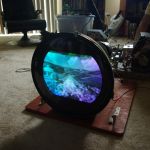
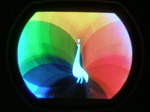
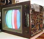
Comparisons before and after FBX replacement.

Here are preliminary comparisons of the original FBX vs the replacement FBX installed in my 21CT55. The screen is still too wide, must be the original yoke is more sensitive then the newer yokes intended to be driven by the replacement FBX. No, I wont try to find a newer yoke………..Tom
Attached Images
File Type: jpg 213-1380_IMG.jpg (95.7 KB, 58 views)
File Type: jpg Copy of 180-8089_IMG.jpg (72.4 KB, 76 views)
File Type: jpg Copy of 214-1429_IMG.jpg (65.4 KB, 66 views)
File Type: jpg Copy of 180-8095_IMG.jpg (87.0 KB, 62 views)
File Type: jpg 214-1426_IMG.jpg (86.8 KB, 71 views)

Last edited by Tomcomm; 02-26-2011 at 05:11 PM.
Reply With Quote
  #144  
Old 02-26-2011, 05:19 PM
Steve McVoy's Avatar
Steve McVoy Steve McVoy is offline
VideoKarma Member
 
Join Date: Oct 2002
Location: Columbus, Ohio
Posts: 1,479
When I had to come up with a flyback for my CBS field sequential color adapter (the original was missing) I had to experiment with various things to get the replacement to work with the yoke. I also had too much width. I added an inductor paralleled by a resistor in series with the yoke. Maybe something similar would work for you:

http://www.earlytelevision.org/cbs_c...storation.html
Reply With Quote
  #145  
Old 02-28-2011, 02:28 PM
Tomcomm's Avatar
Tomcomm Tomcomm is offline
VideoKarma Member
 
Join Date: Nov 2007
Location: Santa Ynez, CA
Posts: 353
Hobble-up Width Control

Steve, thanks for your interest in my 21CT55 reactivation. The new FBX is very efficient, delivering 32kv maximum ultor and 800v boost with B++ of 398v. Fuse current is same as HOT cathode and runs at only 174ma. B++ is limited with power resistors in the power xformer hv secondary so I can select three B++ voltages with 115vac input from my Variac: Low is 374v @ 160ma HOT, Med is 395v @ 170ma HOT, High is 420v @ 182ma HOT. After running for 3 hours at Med, FBX is bearly warm at B++ of 395v. Excessive screen width is the only major problem. All RCA's CTC7 and above have no width control. They must rely on tight spec'd parts in the Horz/EHV system to give just the right over-scan.
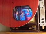
Your experience with using inductors to load the FBX and bleed-off drive to the yoke is consistent with my Fink '57 TV engineering handbook descriptions of width controls . Most of them were shunt where yours is series dropping. I intend to try various schemes to pull mine in.
The preliminary pics I posted above were somewhat disappointing to me. I definitely have chroma leakage in the Q channel since I don't have the proper output filter values installed. Also my camera was on AUTO and bad focus. Here's some full manual pics. The first pic is a stitch of extreme crop of new vs Sony Pro. Q chroma leakage is obvious:
Attached Images
File Type: jpg Copy of Chopped close up RCA Sony 1..jpg (78.4 KB, 63 views)
File Type: jpg Copy of 183-8371_IMG.jpg (88.3 KB, 53 views)
File Type: jpg 214-1465_IMG.jpg (106.0 KB, 52 views)
File Type: jpg Copy of 186-8698_IMG.jpg (75.9 KB, 54 views)
File Type: jpg 214-1466_IMG.jpg (71.6 KB, 49 views)

Last edited by Tomcomm; 02-28-2011 at 03:01 PM.
Reply With Quote
Audiokarma
  #146  
Old 02-28-2011, 03:03 PM
miniman82's Avatar
miniman82 miniman82 is offline
First Light: 1952-2011
 
Join Date: Jun 2009
Location: Great Mills, MD
Posts: 4,159
Quote:
Originally Posted by Tomcomm View Post
All RCA's CTC7 and above have no width control. They must rely on tight spec'd parts in the Horz/EHV system to give just the right over-scan.


My 7 and 9 both have a plug on the yoke you can move around to get the desired width, while my 4 has an actual switch.
__________________
Evolution...
Reply With Quote
  #147  
Old 02-28-2011, 05:03 PM
sampson159's Avatar
sampson159 sampson159 is offline
sampson159
 
Join Date: Sep 2007
Location: columbus,ohio
Posts: 2,170
my 9 has that plug also.these sets produce some of the most pleasing colors.i have it along side of my zenith space command and the 9 s flesh tones are remarkable.my xl100 and the zenith chromacolor with the 25vdmp22 are better,but not that much.love those old rcas!
Reply With Quote
  #148  
Old 02-28-2011, 08:26 PM
old_tv_nut's Avatar
old_tv_nut old_tv_nut is offline
See yourself on Color TV!
 
Join Date: Jul 2004
Location: Rancho Sahuarita
Posts: 7,193
Quote:
Originally Posted by Tomcomm View Post
The first pic is a stitch of extreme crop of new vs Sony Pro. Q chroma leakage is obvious:
What are the other 4 pics? Chroma dots on every other one? - like with and without 3.58 trap in the luma.
Reply With Quote
  #149  
Old 03-06-2011, 02:33 AM
cbenham's Avatar
cbenham cbenham is offline
VideoKarma Member
 
Join Date: May 2006
Posts: 471
Quote:
Originally Posted by trojanrabbit View Post
Of course a flyback is a type of switching power supply (having designed a couple). And sweep tubes were commonly used in lower cost amateur SW transmitters, probably running pretty close to Class C (I think you could get 100W PEP SSB out of a 6JE6). You tuned the final to minimum current.
By the way this is what the horizontal linearity or efficiency coil is for; to tune
the HOT circuit for minimum current which, at least in my B&W sets is also the best linearity. I imagine it's the same in color sets too?
Cliff
Reply With Quote
  #150  
Old 03-07-2011, 12:26 PM
dieseljeep dieseljeep is offline
VideoKarma Member
 
Join Date: Jul 2010
Posts: 7,562
Quote:
Originally Posted by John Folsom View Post
The resistor elimination in the 21CT55 matrix from the CT100 design was a patent dodge. RCA did not want to pay royalties on I/Q demodulation. Well, thats the story I heard. RCA was known to do almost anything to avoid paying royalties.
RCA was the last major mfr. to use intercarrier audio. I guess Sarnoff didn't want to lower himself to paying royalties to Motorola Inc.
Reply With Quote
Audiokarma
Reply


Posting Rules
You may not post new threads
You may not post replies
You may not post attachments
You may not edit your posts

BB code is On
Smilies are On
[IMG] code is On
HTML code is Off

Forum Jump


All times are GMT -5. The time now is 12:46 AM.


Powered by vBulletin® Version 3.8.4
Copyright ©2000 - 2024, Jelsoft Enterprises Ltd.
©Copyright 2012 VideoKarma.org, All rights reserved.