
|
|
|
#31
 02-15-2019, 10:34 PM
|
|||
|
|||
|
I have decided to tackle the board and try to disengage it from everything that's connected to it, so I can not only get at the diode, but take the opportunity to replace any remaining wonky components and check the traces, etc.
I don't have a video signal generator, so I'm going to have to rely on a conventional video source into the antenna input for now, but will try feeding into circuit in an alternate way, if I need to get to that point.  

|
|
#32
02-16-2019, 09:30 AM
|
||||
|
||||
|
It looks like if you can get that bolt and soldered on under board shield off you can work on the board without removing the board.
Be aware if you plan to power it up before fully reassembling it that you will need to jumper any desoldered board ground to chassis. PCBs of this period usually did not have a contiguous ground plane, but instead had a few separate ground traces that each went to one of the board solder mounts...The board solder mount grounds effectively tied together thru the chassis. If any solder mount is disconnected or has a bad joint the portion of the board it grounds will float and the circuits that use those ground points won't work (until reconnected to chassis ground).
__________________
Tom C. Zenith: The quality stays in EVEN after the name falls off! What I want. --> http://www.videokarma.org/showpost.p...62&postcount=4
|
|
#33
02-16-2019, 03:25 PM
|
||||
|
||||
|
A few notes.
How do you service it ? Almost impossible ! My boss couldnt say no to anything. There were still some floating around in the early 70's and he refused to work on them. I dont know how RCA & others built sets like this. Manuals said to cut out or crush then they had little spring like things to make the connection. Video detector diodes were troublesome up till the mid 60's. Often gave odd symptoms so if any question just change the damn thing. When built into a can often the can had a 2 piece shield & the top pulled off so look for that. BTW tube testers are almost a bigger liar than a politician. A known good tube is the only way to be sure. We had a TOTL B&K & never used it. It was for the customers & the biggest obscene profit maker in the shop. 73 Zeno  LFOD !
|
|
#34
02-16-2019, 06:03 PM
|
|||
|
|||
|
I was finally able to work free the can hiding the detector diode. I desoldered one leg of the diode and tested it. It tested "normally" with a drop of .275 and no reverse current. I may replace it anyway, as there may be other problems with it undetectable by my multimeter and after 60 years of use.
  Another idea that ham friend, who is also very experienced in TV repair suggested, was to inject a 1Khz signal (using a .1 uF) along the signal path and see where there's a hard stop. The 1Khz signal should display black bars (according to him) on the screen. Injecting at a point where black bars don't display on the CRT is supposed to indicate the location of failed component. I may see if I can get my hands on a tested/NOS 8AW8A to swap out. Roger on the separated grounds on the board and making sure to clip those to chassis prior to testing. Great call.
|
|
#35
02-17-2019, 01:33 PM
|
||||
|
||||
|
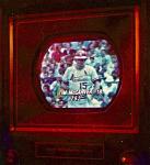
The 1KHz signal may not work that well, unless you traced the signal with a scope. There would be no sync, so seeing bars on the screen would be very unlikely. You don't know how far off your sweep frequencies are free running.
That brings up a point, if you had no sync and the sweep frequencies were off, then a video signal getting to the CRT could have the image jumbled so much it would not be recognizable.
|
| Audiokarma |
|
#36
02-17-2019, 02:02 PM
|
||||
|
||||
|
Quote:
|
|
#37
02-17-2019, 02:12 PM
|
||||
|
||||
|
Quote:
https://stevenjohnson.com/donbosco.htm jr
|
|
#38
02-17-2019, 04:47 PM
|
||||
|
||||
|
Quote:
Quote:
At some point in the ~10 years since I did that, I repeated that experiment on a different set (think I didn't want to dig the right generator out cause I'm lazy) and got the same results.
__________________
Tom C. Zenith: The quality stays in EVEN after the name falls off! What I want. --> http://www.videokarma.org/showpost.p...62&postcount=4
|
 |
| Thread Tools | |
| Display Modes | |
|
|


 Linear Mode

