
|
|
|
#31
 09-27-2014, 11:44 PM
|
||||
|
||||
|
Quote:
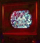
Either earlier here and/or on another related thread I mentioned complete loss of color. I have read that 6GH8 tubes were troublesome for whatever reason. That must have been an understatement as I remember checking the single tube in my set's compliment (which acts as the chroma reference oscillator) a while back and it checked OK, but I can't remember if that test was done on my cheaper Accurate Instruments tester or on my Hickok 6000A. Either way it goes, I pulled the tube tonight and plugged it into my Hickok and the tube was really weak (in the red) on both the triode and the pentode tests. Luckily I had about 8 of them in my used collection and of them all only one came up to the question mark symbol between the bad and good scale on both tests. I thought that it was a bit odd that most of the tubes I had were testing in a very similar range which fell within that ever present "diodes OK" area, I tossed any that were below that point until perhaps I just try them in the set. The one that was dead in the middle (question mark) got put in the set and BAM color at long last!  That's been a long time coming as it's was the first thing to go wrong with the set. Now if I can get that ugly white line (Barkhausen?) out of the left side of the picture and do some convergence work I might be one of those lucky guys who have Zenith color sets that they don't have to post about because they work as is! LOL! That's been a long time coming as it's was the first thing to go wrong with the set. Now if I can get that ugly white line (Barkhausen?) out of the left side of the picture and do some convergence work I might be one of those lucky guys who have Zenith color sets that they don't have to post about because they work as is! LOL!  I'll have to find me a CTC something to keep me busy if this goes right. I really don't have time anymore for a proper recap if repair is all that is needed. We will see..... I'll have to find me a CTC something to keep me busy if this goes right. I really don't have time anymore for a proper recap if repair is all that is needed. We will see.....
__________________
"Face piles of trials with smiles, for it riles them to believe that you perceive the web they weave, and keep on thinking free" 
|
|
#32
09-28-2014, 08:04 AM
|
||||
|
||||
|
If'n yer wanting to experiment on that Barkhausen thing..... I have 2 of the same model set
and they both have OEM Horizontal output tubes still in them, and they both have an ion trap on them about midpoint on the tube. I got the Sams for the set, and they have the ion trap on from the factory, and an explination as to why the trap is there.... and yes they say it's the "B" Barkhausen. So If you want to, get a small magnet, hold it so you don't get a shock, like tir it to a wood stick, and move it near the side of the tube and see what happens.... But if it's the tube that the set calls for, and it's a good one, it's possible the problem is something else.... Like your mini aurora show..... I have found the best thing to do for that is to clean everything near it with windex, then let it dry for a few days. And for the slug in plastic coils, chapstick is the best plastic safe lube to use.... It don't take much, apply with Q-tip inside the coil, then wind the slug in..... Good Luck.... On the other thing.... You should check voltages on the Horizontal output tube, before and after the shift in current. Do any of them change, even a little... That may be a clue... Remember bias on G1 to a good degree dictates cathode current..... Is it runaway or not....? Good thing to look into that screen grid cap as mentioned too.... .
__________________
Yes you can call me "Squirrel boy" Last edited by Username1; 09-28-2014 at 08:10 AM.
|
|
#33
09-28-2014, 10:15 AM
|
|||
|
|||
|
Before reading Username1's post, i was gonna say..
if you don't want to do a recap, at bare minimum replace the coupling cap going to G1 of the H out tube. Then he sed the same thing. The slightest leakage in that cap will push the grid more positive.
|
|
#34
09-28-2014, 12:15 PM
|
||||
|
||||
|
Quote:
Yup.... There's 2 votes fer checkin the bias on the Horiz. Output tube.... Even if you decide to just change it, check the voltages first. It will possibly be the only "test" of the cap, just in the small leakage there may be, even if any possible cap. test itself may never reveal it to be bad, a higher G1 voltage may be the perfect load test to show it's really bad.... .
__________________
Yes you can call me "Squirrel boy"
|
|
#35
09-28-2014, 01:52 PM
|
|||
|
|||
|
But don't just check it; replace it as a matter of course. Same with the coupling cap going to G1 of any power stage (like audio out, vert. out etc.) since power stages are the most vulnerable to overcurrent.
|
| Audiokarma |
|
#36
09-29-2014, 12:32 AM
|
||||
|
||||
|
Quote:
I like the sound of the Chapstick idea for the slug as long as I can get the old one out. It seems to be disintegrating for whatever reason, so I keep thinking that I should get it out and put in the very much intact slug from the old unit that I removed with disintegrated plastic. On the flip, Old_coot88 suggests leaving it be as it would not be the problem if I had runaway current. It's only a fine tuning to my knowledge. Some earlier mentioned tube swapping caused and re-swapping rectified the runaway current which led me to discover the stuck slug trying to control it in a bit of haste. Right now she is holding a steady 210mA which is supposedly acceptable. Now, to the G1 capacitor and biasing. I have not yet had time to check any voltages and it sounds like the right thing to do is simply replace such a critical cap. Looking at the schematic I see a .01mfd (C66) to pin 5 of the H.O. tube 6HF5 via a 100 ohm resistor. There is also a .001mfd @ 10% (C65) in parallel to that going through a 33K ohm resistor to ground. Admission of guilt on limited knowledge leads me to ask which of these is the right one. My bet is on the .01mfd going straight to G1, but I want to make sure along with getting a more firm understanding of these circuits. This is great information once again folks! Thanks so much!
__________________
"Face piles of trials with smiles, for it riles them to believe that you perceive the web they weave, and keep on thinking free"
|
|
#37
09-29-2014, 07:12 AM
|
||||
|
||||
|
Hi !
I believe I was unclear, I have 2 sets of the same model, but NOT the one you have. What I mean is that the sets I have are 1958 Emerson B&W tv's and both were made with a built in problem that required the ion trap on the H Output tube. Onto the coupling cap. Since you believe you have a current problem, knowing that you have found the problem part, and actually fixed the problem is the reason you would want to check voltages Before, and After replacing the coupling cap. on this issue..... It is a way to learn, and help those who follow this problem on this thread learn too.... If you just blindly replace the cap, did anything change...? Was a bias voltage change the reason for the higher current ? Did you fix it or not ? If the slug in the coil is broken, remove the coil and drill out the broken slug, start with a drill just a little bigger than the hex opening, then go up from there. Eventually you will have broken pieces, and have to knock or unscrew them out with steel wire, or very small drill bits. Unless you can get a new coil and just replace the entire thing. .
__________________
Yes you can call me "Squirrel boy" Last edited by Username1; 09-29-2014 at 07:24 AM.
|
|
#38
09-29-2014, 08:50 PM
|
||||
|
||||
|
Quote:
I gave some specifics last night on G2 coupling capacitors and what I see in my schematic. Will someone look that information over and give me a short lesson in coupling and which of the two capacitors mentioned would be the coupling cap. Again, the one that goes straight from tube to tube would be the logical choice, but I could easily be wrong. Being that they are both in this critical circuit, it would be smart to get rid of them both. I will have to see what type they are to pass some judgement. There are actually two or three "bumblebee" caps in this set that I know need to go. I think the black beauties have a bad reputation as well. There was one of those across the windings of my old efficiency coil. The old brown 'drops' are probably the best as they are not paper/foil like the others.
__________________
"Face piles of trials with smiles, for it riles them to believe that you perceive the web they weave, and keep on thinking free"
|
|
#39
09-30-2014, 02:43 PM
|
||||
|
||||
|
Quote:
jr
|
|
#40
09-30-2014, 03:27 PM
|
||||
|
||||
|
This is a typical coupling capacitor used between stages. It's the AC signal
path from the output (plate) of a previous stage, to the input (grid) of the following stage. Not all configurations are the same, it is easiest to spot if you are following the AC signal path, as a job of the coupling capacitor, is to pass the amplified signal to the next stage, but block the DC voltage from the plate, or collector circuit if it's a transistor amplifier. And again some configurations will be different. In the IF sections of your tv coupling between stages is done with a coupling transformer, there is a load resistor after the transformer, but the transformer passes only the changing signal amplitude from one side, to the other side, so again DC is blocked. .
__________________
Yes you can call me "Squirrel boy" Last edited by Username1; 09-30-2014 at 03:33 PM.
|
| Audiokarma |
|
#41
10-01-2014, 07:24 PM
|
||||
|
||||
|
Thanks a lot "Squirrel Boy" for the fine explanation and pictorial. The two definitely give me a better understanding of the circuit and will allow a clearer explanation of what I see in my schematic.
My .01mfd certainly goes from the plate of the horizontal oscillator to the grid of the output tube same as C85 in Username1's pic. So that is the true representation of a coupling cap. The .001mfd going through the 33Kohm resistor is positioned just as C84 is in Username1's pic only there is a ground symbol at the end. That pretty much has them in parallel. In the picture a load resistor is pointed out. Mine seems to be a 2 watt 82Kohm unit. Finally the picture shows an R127 going to chassis ground. There I have a 10Meg. This may be a useless comparison to some folks, but it is helping me a lot in learning and that's often what we are here for. Parts swapping is more or less taking the low road. Not that it's all I know, but I am often guilty of it. I want to start using my oscilloscope more than I do. I know "TV repairmen" who seldom if ever use one, but it is certainly one of the more important tools in the electronics arsenal. Thanks again everyone and when I make some changes or other accomplishments I will be sure to update.
__________________
"Face piles of trials with smiles, for it riles them to believe that you perceive the web they weave, and keep on thinking free"
|
|
#42
10-02-2014, 02:27 PM
|
||||
|
||||
|
There are many different tools that you can or need to use at different times
to repair any item, tv car, vacuum. I have found most repairs were actually made using observation, block diagrams, walking through what was happening in my mind, using a voltage or ohm meter. Oscilloscope was not too often the first tool I went to for a lot of troubleshooting. While looking for examples of coupling capacitors on the internet I was not able to find a good tube example, so I took that one from a tv. I did find a really really really good page with some design stuff on it. Now you don't have to do any math to see what it going on, and you can follow the examples pretty easily, just let it work in.... http://dc213.4shared.com/doc/Te4Wew3A/preview.html I believe this is a test page for someones website, so it may not be up too long.... I would download it and save it.... .
__________________
Yes you can call me "Squirrel boy"
|
|
#43
10-04-2014, 04:40 AM
|
||||
|
||||
|
Interesting link. Unfortunately transistor based, but I guess coupling is coupling, and I did want a better understanding. Thanks!
__________________
"Face piles of trials with smiles, for it riles them to believe that you perceive the web they weave, and keep on thinking free"
|
|
#44
10-04-2014, 10:14 AM
|
||||
|
||||
|
Transistor Base = Tube Grid
Transistor Collector = Tube Plate Transistor Emitter = Tube Cathode For basic NPN transistor. But tubes are Voltage Amplifiers with near infinite input impedance, and your basic transistor is a current amplifier.... I think its FETS that are close to tubes in the respect to no base current. Coupling is coupling as far as signal goes.... because it is amplifier stage to amplifier stage, so its ac signal coupling. And there are books where you can find the same stuff but with tube examples. They may just be a little harder to find... .
__________________
Yes you can call me "Squirrel boy"
|
|
#45
10-04-2014, 09:16 PM
|
||||
|
||||
|
I like the comparison as I have an understanding of both and many of their capabilities, and I know rudimentary circuit applications for the transistor as our labs in college naturally in modern times were transistor based. I am lucky enough to have gotten my feet wet in a time when we studied both vacuum tube and transistor theory and application along with the God given opportunity to know how to use an analog V.O.M. Seems like our class had Simpson 260s and I don't ever remember digital anything although I know that they existed.
So, somehow I always looked at tube circuits or devices as one thing and solid state as another. So much for hybrids I guess. As far as books I have quite a library of vintage electronics books including a complete 1940s National Radio Institute (N.R.I.) correspondence course textbook set. Only a few of my books come up into the transistor era which never bothered me as my more modern college books cover all of that and of course the digital realm. So again, thanks for the section by section comparison. Now, I need to find those two caps in my horizontal output circuit and get them replaced along with taking some voltage measurements and get them posted. For now I'm not going to worry with scope waveforms as I think it would really just throw me off track in my true understanding of the circuits and their behavior.
__________________
"Face piles of trials with smiles, for it riles them to believe that you perceive the web they weave, and keep on thinking free"
|
| Audiokarma |
 |
|
|


 Linear Mode

