
|
|
|
#31
 03-12-2011, 10:44 PM
|
||||
|
||||
|
Quote:
Ron L actually came up with the correct basing over on ARF. Quote:
 Kevin 
|
|
#32
03-13-2011, 02:01 PM
|
||||
|
||||
|
As for the smearing issue, the longer CRT wires from the socket to the test jig will cause that to occur.
It has been years since I've used or been around a jig but at one of my first jobs in a shop during the mid-seventies we had a Tele-Matic model jig. (I remember that smearing!) It wouldn't support roundies so we used a gutted CTC-10 metal cabinet set mounted at the end of the bench.
|
|
#33
03-13-2011, 02:26 PM
|
|||
|
|||
|
I started using a jig in the early 70's. The Telematic jig did in fact support the round crt type chassis. So did the RCA jigs as well as the Sylvania jigs.
|
|
#34
03-13-2011, 02:41 PM
|
||||
|
||||
|
Quote:
|
|
#35
03-13-2011, 02:50 PM
|
||||
|
||||
|
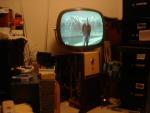
Thanks for the comments. I suppose the stray capacitance with the longer CRT cable is causing ringing. I'm also seeing some green ghosting behind images, that I suspsect is because of the green gun leakage in my jigs CRT. Also, the convergence is so poor on this CRT, that I'm seeing multi colored images of text on the outside edges of the screen.
Are there any newer larger rectangular CRT's that are functionally equivalent to the 21FJP22? Kevin Last edited by Kevin Kuehn; 03-13-2011 at 03:02 PM.
|
| Audiokarma |
|
#36
03-15-2011, 12:42 AM
|
||||
|
||||
|
As others said, since there is way to send dynamic convergence signals from the specific chassis being tested to the jig, the jig's CRT will have poor convergence everywhere except its center area (which should be able to be adjusted using static convergence components on the back of its CRT).
There could not be a truly "equivalent" rectangular CRT to match the roundies, since round-CRT chassis do not have pincushion adjustments, for example. I would also expect a rectangular CRT's yoke to be different as well, perhaps significantly. If you have access to them, try comparing a CTC-16 schematic to a CTC-17; those are probably pretty close except round vs. rectangular. Are you missing your yoke programmer and/or convergence load (CVL) devices from your CK-3000? I know the CVL is really just a resistor (as discussed earlier in this topic), but I don't know about the yoke programmers, however, I could try to measure mine to help you make your own replacement.
__________________
Chris Quote from another forum: "(Antique TV collecting) always seemed to me to be a fringe hobby that only weirdos did."
|
|
#37
03-15-2011, 12:32 PM
|
||||
|
||||
|
Quote:
Thanks for the pointers. As you can tell I have very little experience working on color, or even b&w TV's. I went to school for some of this way back in the early 80's, but unfortunately was never able to apply any of it until becoming interested as a hobby. Now it's like learning all over again, and I'm a pretty slow learner unless I can put things into actual practice. I understand the lack of dynamic convergence issue on the jig, I just didn't realize how dramatic it would be without the adjustments. We're talking horizontal color separation of 1/8-1/4" at the outer edges. I made my own CRT adaptor, CVL and Yoke programmer. My CK3000 came with a 1990/91 supplementary setup manual; they actually have the Yoke jumper connections listed for the various inductances in the back of the manual. For an YP12 (12.6 mH) I have pins 1&7 and 2&3 jumpered. Setting up this test jig has been a good learning experience in itself. I even accidentally found out that I can run my 21FJP22 without the CTC-11 convergence board plugged in. It looks very similar to the test jigs very poor convergence. Kevin Last edited by Kevin Kuehn; 03-15-2011 at 12:36 PM.
|
 |
| Thread Tools | |
| Display Modes | |
|
|


 Linear Mode

