
|
|
|
#77
 11-12-2017, 09:08 PM
|
|||
|
|||
|
Quote:

|
|
#78
11-12-2017, 09:17 PM
|
|||
|
|||
|
I did a terminal strip located near the front of the chassis. It was pretty much self contained and consisted of just a few parts.
 During the removal of the old parts, I noticed that there was that yellow CAD plating residue on parts of the terminal strip.   What I do to clean off that residue is I use CLR cut 50/50 with water. I brushed on a little with a cut down acid brush to about 1/2 inch long. I then "scrub" the area with the acid brush. Then I mop up the area with paper towels, Q-Tips, and alcohol. The residue comes off very easy this way.  I then replaced the components and cleaned off the flux, and I'm done.  Since this picture was taken, I added some more solder to the lower ground terminal. Last edited by Crist Rigott; 11-12-2017 at 09:22 PM.
|
|
#79
11-13-2017, 11:55 AM
|
|||
|
|||
|
Moving to the upper part of the chassis I decided to do the terminal strip near T3.
Pretty routine and nothing special to report except I had to lengthen a lead on R84 a 100 Ohm resistor. What I do is trim the one side to about 1/4 inch length. I then use some 22awg bus wire and attach it to the trimmed lead using the coil method. I then figure out how long the lead needs to be and slide a piece of 1/16 inch heat shrink tubing down to the coil. I then shrink the tubing and then use a 1/4 inch long piece of 1/8 heat shrink tubing to cover up the coil.    
|
|
#80
11-13-2017, 11:15 PM
|
|||
|
|||
|
Did some work around V9. Here are the before and after pictures.
  And some around V14.   And an over all picture of my progress. 
Last edited by Crist Rigott; 11-13-2017 at 11:23 PM.
|
| Audiokarma |
|
#81
11-15-2017, 09:25 PM
|
|||
|
|||
|
My high voltage wire came in so I finished the Flyback wiring. I decided to use some new 20Kv 22awg wire. I've used this stuff before and it has worked well for me. The working H.V. is about 12 to 14Kv.
I used some heat shrink to increase the diameter of the wire and to provide some extra abrasion resistance as it passes through the then guides. I then soldered it to the 1B3GT tube socket and used several layers of heat shrink tubing to provide some extra strain relief on the wires as they go into the tube socket. I then used some lacing cord to tie the wires together before they go into the tube socket shell. I also used some of this wire for the plate cap wire for both 6BQ6GT and the 1B3GT tubes. I'll terminate the CRT HV lead during the dry fit phase.     
|
|
#82
11-16-2017, 07:55 PM
|
|||
|
|||
|
OK guys, I have some questions for the disc capacitors in this TV. I know they should be good, but I tested one and it was 50% high. So I'm thinking that maybe I'll replace them. There are only 10 of them.
My question is what do I use to replace them? I know I need ceramic disc and I'm thinking of getting 1KV type. I know there are by-pass and coupling caps. Do I get COG, NPO, Z5U, Y5P, etc? Below is a simple chart I made up that shows the SAMS parts list and the cross for each size cap. Also the Item Number of each cap. I checked the old Allied Catalog archive but they don't really list the specs for those caps. Any help would be appreciated. 
|
|
#83
11-16-2017, 08:37 PM
|
|||
|
|||
|
I have finished the main chassis except for the IF Strip.
We, the VRPS of Dallas, has our annual convention this weekend so there will be very little work and posting on my progress. 
|
|
#84
11-17-2017, 11:25 PM
|
|||
|
|||
|
I looked up your disc cap numbers in a 1953 jobbers catalog. Z5U and 5YP type caps will work fine. The originals were rated for 500 working volts DC or better. The tolerances were 20%. The .01 cap should be 600vdc or better according to one brand.
Ed
|
|
#85
11-17-2017, 11:29 PM
|
|||
|
|||
|
Great information. Thanks Ed.
|
| Audiokarma |
|
#86
11-18-2017, 05:18 PM
|
||||
|
||||
|
On the electrolytic's heating concern: I tend to believe ambient heating from transformer and tubes is the dominant factor, but I suppose there could be a small accumulative effect. Many manufactures mounted cans under chassis with little concern for airflow. At any rate it would be interesting to check their temperatures relative to surrounding surfaces of the chassis.
|
|
#87
11-20-2017, 11:32 PM
|
|||
|
|||
|
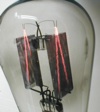
During this weekend swap meet at our annual convention, I managed to get a few "donor" E-Caps for C4. This E-Cap is the smaller diameter kind.
I restuffed it basically the same way as the others. I use some R/C wing tube that I had after building a model. This stuff works great. I kept the caps out of the sleeve because they put a slight pressure on the sleeve and I thought it would deform the round sleeve. I haven't cleaned out the cans yet.     
|
|
#88
11-21-2017, 10:27 PM
|
|||
|
|||
|
The bottom side of the chassis is done. Every resistor, film cap, electrolytic, disc, and mica cap was replaced. Now on to the topside. The HV cage, tuner, yoke, etc.

|
|
#89
11-22-2017, 04:51 PM
|
|||
|
|||
|
I replaced all of the resistors in the tuner today. 3 of them were a bit tough. I relied on the coil method for those 3 and a few other places. I cleaned the tuner assembly and then replaced the resistors. I then used De-Oxit and a business card to clean the fingers where the tuning strips slide through.
As a side note the average the resistors were 23% from their nominal resistance. The lowest was 3% and the highest was 62%. Of the 9 resistors replaced, 5 were way out of tolerance, 2 were 12% (just out of tolerance), and 2 were 3% (well within tolerance). Pretty close to what I've seen through the 6 chassis I've restored. Where at least 50% were out of tolerance. 25% were just out of tolerance, and 25% were with in tolerance.     
Last edited by Crist Rigott; 11-22-2017 at 05:14 PM.
|
|
#90
11-23-2017, 10:38 PM
|
||||
|
||||
|
As a still-improving restorer, I love reading these thorough restoration discussions and picking up new techniques and correcting my improper methods. I learn so so much from these detailed walk-through restorations!
|
| Audiokarma |
 |
| Thread Tools | |
| Display Modes | |
|
|


 Linear Mode

