
|
|
|
#31
 09-08-2013, 08:42 PM
|
||||
|
||||
|
Quote:
If I crank up the contrast, the dark bars get lighter until the match the existing lighter bars. So if I crank it up, the entire screens becomes over saturated and it's pretty hard to see the bars (pretty sure they're still there). Should I be looking for ground points only in the horizontal circuit? It's pretty crazy trying to find out all the ground points on all the terminal strips and such. Only the ground points of the modules are noted. All others have to be located manually. Not an easy process. I'm going to replace the voltage divider as the current only is leaking. On humid days it buzzes and has a blue corona. If you put your finger near it, it tries to reach out and touch you. Could this cause the moire? I believe the scope I am using goes up to 500 kHz. I also got a new x10 probe. I just have to figure out what ringing would look like when comparing the wave I get to the one in the SM.
__________________
Pioneer SX-1080, Pioneer PL-115D, Pioneer CT-F9191, Pioneer RG-1, Wollensak 8050A, Akai 4000DS MkII, Pioneer CS-05 & Polk 1.2TL Denon 5803A, Pioneer DVL-700, Pioneer CT-W603RS, Toshiba HD-A3, D-Link DSM-520, Dish VIP-722, Polk 1.2TL, CSi5, LS/fx, RT-800 and PSW-650 
|
|
#32
09-08-2013, 09:00 PM
|
||||
|
||||
|
Quote:
__________________
Pioneer SX-1080, Pioneer PL-115D, Pioneer CT-F9191, Pioneer RG-1, Wollensak 8050A, Akai 4000DS MkII, Pioneer CS-05 & Polk 1.2TL Denon 5803A, Pioneer DVL-700, Pioneer CT-W603RS, Toshiba HD-A3, D-Link DSM-520, Dish VIP-722, Polk 1.2TL, CSi5, LS/fx, RT-800 and PSW-650
|
|
#33
09-08-2013, 09:13 PM
|
||||
|
||||
|
Quote:
jr
|
|
#34
09-08-2013, 09:35 PM
|
||||
|
||||
|
Quote:
My suggestion is to try connecting known ground points directly to where they are supposed to go in case the connectors on the PC boards are still not making good contact even though you cleaned them. Also, you can try connecting different ground points on the PC board connectors to each other to see if that helps. What is the maximum gain (volts/division) that your scope has? Depending on where in the circuit, you may need more gain than your scope provides to see this waveform, especially if you use a 10x probe. Your scope needs to be synced to the horizontal sweep. If you cannot sync it independent of the probe input, it will be next to impossible to trace the waveform. You definitely then need a better scope. If the scope is locked to horizontal sweep and showing at least one complete sweep cycle, the jail bars will appear as a sine wave of decreasing amplitude from left to right, with about 10 or 12 cycles within one horizontal sweep (as you can count by looking at the TV screen). This decaying sine wave will be added on top of whatever normal waveform is at the place you are probing.
|
|
#35
09-08-2013, 09:39 PM
|
||||
|
||||
|
Quote:
|
| Audiokarma |
|
#36
09-08-2013, 10:13 PM
|
||||
|
||||
|
Quote:

__________________
Pioneer SX-1080, Pioneer PL-115D, Pioneer CT-F9191, Pioneer RG-1, Wollensak 8050A, Akai 4000DS MkII, Pioneer CS-05 & Polk 1.2TL Denon 5803A, Pioneer DVL-700, Pioneer CT-W603RS, Toshiba HD-A3, D-Link DSM-520, Dish VIP-722, Polk 1.2TL, CSi5, LS/fx, RT-800 and PSW-650
|
|
#37
09-08-2013, 10:27 PM
|
||||
|
||||
|
Quote:
The scope has a X1, X10 and X100 setting and the probe has X1 and X10. I'm not sure what the maximum is, but I understand this one can handle all the way to the yoke and high voltage. The scope can either sink with the probe, it's internal (using the AC line, I believe) and an external source (of which I don't have). Where in the horizontal should I start? Should I start at the HOT and work my way back?
__________________
Pioneer SX-1080, Pioneer PL-115D, Pioneer CT-F9191, Pioneer RG-1, Wollensak 8050A, Akai 4000DS MkII, Pioneer CS-05 & Polk 1.2TL Denon 5803A, Pioneer DVL-700, Pioneer CT-W603RS, Toshiba HD-A3, D-Link DSM-520, Dish VIP-722, Polk 1.2TL, CSi5, LS/fx, RT-800 and PSW-650
|
|
#38
09-08-2013, 10:35 PM
|
||||
|
||||
|
Quote:
__________________
Pioneer SX-1080, Pioneer PL-115D, Pioneer CT-F9191, Pioneer RG-1, Wollensak 8050A, Akai 4000DS MkII, Pioneer CS-05 & Polk 1.2TL Denon 5803A, Pioneer DVL-700, Pioneer CT-W603RS, Toshiba HD-A3, D-Link DSM-520, Dish VIP-722, Polk 1.2TL, CSi5, LS/fx, RT-800 and PSW-650
|
|
#39
09-09-2013, 08:51 AM
|
||||
|
||||
|
Sorry I have very few Sams. Not to throw more confusion into this, but this is a video that goes over the concept of O'scope bandwidth, and is good for your problem.
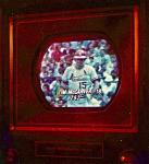
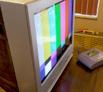
http://www.youtube.com/watch?v=oZ1Dv2dVGkU After the 2:50 point he starts getting into the "ringing" on an otherwise low frequency oscillator, and the bandwidth you will need to find your problem. This video shows a little about roll off and why your scope should have a bandwidth well above what you actually want to be able to measure. And it all comes down to what makes up a wave form. He does not go into it here, but a square wave of 1khz actually needs a bandwidth multiple times that 1khz to be accurately displayed on an oscilloscope. http://www.youtube.com/watch?v=pGwL6FadC9U Your oscillation is about 10X horiz scan rate, easy to see as you have at least 10 visible vertical bars on the screen, As stated, around 200K, so you will need a scope that has a 1mhz bandwidth to see the ringing clearly. The above video explains the roll off of the scope, and why partly the bandwidth should be 1mhz. He is correct in this. Another person asks if the bars get darker if the contrast knob is turned. With the same white screen, no signal, when turning the contrast knob through its range, does the bars change in their appearance? If not the noise is getting in other than the video amplifier circuit, (power supply because of bad decoupling cap) if they change significantly then the noise is being amplified by the video amplifier. So its a signal level noise. Regardless of how the noise gets in, its source is likely at some point in the horizontal section. It is possible it can come from your corona source, does it intensify as you do something to cause the field to come close to arcing? Other than that, there are two attached pictures from a tv I own, its not yours, but it shows parts near the horiz. area that can be culprits of your problem. Suspect any parts near the red dots, resistors, caps, inductors. You should go to the Sams website and buy your tv schematic, look around in the same parts of the tv, Horiz Osc, Driver, and output stages. There are two red arrows on one of the pictures, they point to waveforms that are capable of generating the "ring" because they are a pulse, and are squared. If a part that is designed to filter out overshoot in the pulse rise is bad, then the circuit, or following stage will momentarily oscillate at a higher frequency and give you that ring, and go into another part of the tv and give you those vertical bars...... Do not overlook shielding, of any parts, picture tube, or grounds. This is a likely description of what could be causing those bars, its your job to look for a bad part in those areas, you will likely need the Sams, and possibly a good scope, and (2) 1mhz - 5mhz 10X to 1X probe with capacitance trimmer built in. There are good, inexpensive 20mhz - 100mhz Tektronix scopes and cheap starter grade probes that can be had for around $100. + Shipping, sometimes less. (Yes go for more than a 1mhz scope) You may need a second probe to connect to a horiz sweep sync source, as stated be another, so you better get two.
__________________
Yes you can call me "Squirrel boy" Last edited by Username1; 09-09-2013 at 09:13 AM.
|
|
#41
09-09-2013, 11:57 AM
|
||||
|
||||
|
Even with a good scope, you may or may not be able to see the ring in the wave form. First Sams will have to had put it in the schematic, Its always possible they just don't chose to show a spot that happens to be the source of this specific problem, and second, you/he would have to be able to pick up on it, and then be able to figure out where its coming from. If it's not confined to one spot, its possible it shows up all over the set, then its back to checking individual parts. And who knows, it could be coming from the flyback, and just transmitting that into some near by improperly shielded item. Anyway, it looks like its a big enough disturbance that it can be tracked down.
__________________
Yes you can call me "Squirrel boy"
|
|
#42
09-09-2013, 12:28 PM
|
||||
|
||||
|
Quote:
As for the bars and contrast.... The bars don't change in width or shape when turning up the contrast, but they do get lighter as the screen gets brighter. They almost get light enough to match the lighter bars, but you can still see them if you look. So I'm not sure if I'm doing it the way requested and/or understanding how to look properly for the type of change asked about. I do have the Sams for this chassis. I have the PDF version, but it's too large to put sections up here. Thanks for the links. I'll go over them as many times as necessary to fully understand. Thanks!
__________________
Pioneer SX-1080, Pioneer PL-115D, Pioneer CT-F9191, Pioneer RG-1, Wollensak 8050A, Akai 4000DS MkII, Pioneer CS-05 & Polk 1.2TL Denon 5803A, Pioneer DVL-700, Pioneer CT-W603RS, Toshiba HD-A3, D-Link DSM-520, Dish VIP-722, Polk 1.2TL, CSi5, LS/fx, RT-800 and PSW-650
|
|
#43
09-09-2013, 12:32 PM
|
||||
|
||||
|
Quote:
I think I asked this before, but would a leaking voltage divider cause an issue? I know the top of mine leaks and I have a replacement for it. Just got it and was planning on installing it.
__________________
Pioneer SX-1080, Pioneer PL-115D, Pioneer CT-F9191, Pioneer RG-1, Wollensak 8050A, Akai 4000DS MkII, Pioneer CS-05 & Polk 1.2TL Denon 5803A, Pioneer DVL-700, Pioneer CT-W603RS, Toshiba HD-A3, D-Link DSM-520, Dish VIP-722, Polk 1.2TL, CSi5, LS/fx, RT-800 and PSW-650
|
|
#44
09-09-2013, 12:40 PM
|
||||
|
||||
|
Quote:
__________________
Pioneer SX-1080, Pioneer PL-115D, Pioneer CT-F9191, Pioneer RG-1, Wollensak 8050A, Akai 4000DS MkII, Pioneer CS-05 & Polk 1.2TL Denon 5803A, Pioneer DVL-700, Pioneer CT-W603RS, Toshiba HD-A3, D-Link DSM-520, Dish VIP-722, Polk 1.2TL, CSi5, LS/fx, RT-800 and PSW-650
|
|
#45
09-09-2013, 12:58 PM
|
||||
|
||||
|
If you replaced the Horiz osc board with a known good one, move on, If you have a known good voltage divider and want to replace it, do so, then move on. With parts of the Horiz. circuit out of the way, move on over to the flyback, and parts that may be mounted near it.
You will have to check items on the chassis that are part of the horiz. that are not on the module. When you say diodes had their leads cut then resoldered, did they cut one side, then resolder, or cut both sides...? Both sides may mean they chose to replace the part from on top of the board, I have seen that before, cutting one side may just be to test it with a vom.
__________________
Yes you can call me "Squirrel boy"
|
| Audiokarma |
 |
|
|


 Linear Mode

