
|
|
|
#61
 07-08-2015, 04:11 PM
|
|||
|
|||
|
I am seeking some answers about replacing the selenium rectifiers with silicon diodes. I plan to leave the old ones in place for the nostalgic effect, but I do have a question for you guys. Since the selenium's drop voltage (maybe 10 to 25 volts), has anyone had any experience of what value and wattage resistor(s) to put into series with the diodes to limit excessive voltage to the power supply and the rest of the set. I obviously plan to replace all of the electrolytic's in the set (most with higher voltage ratings), but I still don't want to "cook" the set with too much B+ voltage. I have searched the web and this site and found all kinds of different answers, including putting in no resistors at all. The set is my "new" 21CT55, CTC2B, 1954 color. Of course the answer may just be taking a variac and substituting different values until the find the correct voltage (400 volts) at 120 volt line voltage as published in the Sams schematic. The line voltage at my house usually runs around 125 volts just for your information.

|
|
#62
07-08-2015, 05:56 PM
|
||||
|
||||
|
If I were in your shoes (I am actually, fellow 21CT55 owner), I'd always run my sets on a variac and monitor input AC voltage to make sure it's receiving the rated 117 VAC stated in the schematic. Higher voltages tend to cook irreplaceable parts, and I don't fancy trying to locate a flyback for any of my sets. I'm a big stickler on horizontal/HV circuit adjustments too, and it's served me well in collecting TV's.
I tried to find a resistor/diode substitution that worked well on my CTC-4, and in the end wound up with one of those adjustable high wattage resistors so I could home in on the perfect value without spending too much cash. Something in the 100-ohm range that is adjustable usually works, that way you can slide it around from 0-100 to see what the set likes. Just remember: if you do this while running the AC input at 117 VAC, you must always use a variac or B+ will still be too high if you forget. Most simply plug the set directly into the wall, then set the series resistance to whatever it needs to be for proper B+ readings. The tube filaments won't care about a couple extra AC volts on the line, but the effect is dramatic when looking at horizontal output cathode currect. A few input volts ends up spiking it higher than you'd expect, so monitor things and zero in on the best set of variables for it.
__________________
Evolution... 
|
|
#63
07-08-2015, 06:07 PM
|
||||
|
||||
|
I ended up with a 40 Watt 4 Ohm resistor in series with the 4.5 Amp fuse to get my voltage down. I used two 20W 8 ohm resistors in parallel. You will probably need to experiment to find the right value.
Dave
|
|
#64
07-08-2015, 07:46 PM
|
|||
|
|||
|
Sometimes it's handy to use the 6.3VAC heater rail as a proxy.
If it's over the nominal 6.3V, a little droppage on the primary side is in order to get it back down. And then get the appropriate droppers on the replacement B+ silicons.
|
|
#65
07-09-2015, 06:16 PM
|
|||
|
|||
|
It seems as if a 100 ohm adjustable resistor would be kind of high in value. I agree that an adjustable resistor is the way to go, that way I can get the exact B+ voltage by setting the resistor so that I get the required 400 volt by adjusting it. I am thinking more in the 10-25 ohm range with adjusting it to the close end would be 0 ohms and maybe like 10-25 ohms at the far end. If Zenith 6S621 achieved the proper voltage using just 4 ohms, a 100 ohms resistor would be adjusted all the way to the end. I found out that I can re-stuff at least the main filter cans, so I'm going to give it a try.
|
| Audiokarma |
|
#66
07-09-2015, 06:36 PM
|
||||
|
||||
|
I think you are splitting hairs. These sets were designed to operate over a wide range of line voltages, and differences in components in individual sets will result in quite a variation in DC voltages.
I wouldn't worry about getting the DC just right. Even if you got the 380 v line right, the others won't match what you read on the schematic. Put a small resistor in series with the diodes and you will be fine. In fact, I don't think you'd have a problem with not using a resistor. You might end up with 20 or so volts more on the DC, which won't be a problem.
|
|
#67
07-09-2015, 07:04 PM
|
|||
|
|||
|
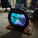
I think your right Steve, I know most all older electronics ran a tolerance of at least 10% or more. Sometimes I don't know why I'm such a perfectionist. I'll probably slap a 4 ohm resistor in series with the B+ and check the voltage. If it's within 10 volts or so, I'll call it good. Also I found a bunch of peaking coils open. Those little round white ones, mostly in the video circuits. Thanks to the internet, I'm sure I can find most of the correct (or close) values online. One of them is located in the center of the attached picture.
|
|
#68
07-09-2015, 07:49 PM
|
||||
|
||||
|
In my experience all the white, powdery inductors should be replaced. The yellow ones seem to hold up well. I got mine for a recent CT-100 restoration from Newark, like these:
http://www.newark.com/bourns-jw-mill...d=800000016501
|
|
#69
07-09-2015, 10:29 PM
|
||||
|
||||
|
Quote:
Only way to know if you're safe is checking horizontal output tube cathode current, if it's too high you risk a meltdown. Check the Sams on the set, it should have the values you need.
__________________
Evolution...
|
|
#70
07-10-2015, 12:21 AM
|
||||
|
||||
|
As to replacing the selenium, some guidance, first from International Rectifier, as found on the back of their 1965 "Universal Silicon Replacement Rectifier" rated 600V at 1 Ampere.
The second photo is guidance from Sarkes Tarzian, a maker of both Selenium Rectifiers and later, Silicon replacements. This was an enclosure with their M150 "Silicon TV Replacement Rectifier" from the late 60s. It is only rated at 360V, 150mA, obviously aimed at Black and White sets, but it too recommends adding a dropping resistor. Others here have some great advice as well.
__________________
Brian USN RET (Avionics / Cal) CET- Consumer Repair and Avionics ('88) "Capacitor Cosmetologist since '79" When fuses go to work, they quit! Last edited by Findm-Keepm; 09-29-2017 at 06:38 PM.
|
| Audiokarma |
|
#71
07-10-2015, 12:23 AM
|
|||
|
|||
|
Quote:
That's why the earlier suggestion of using the 6.3 VAC heater supply as 'standard marker' when line voltage supply is over spec.
|
|
#72
07-10-2015, 06:49 AM
|
||||
|
||||
|
I think it makes sense to install a small resistor in series with the diodes, but beyond that I think no other precautions are needed. I install fuses in the cathode of the horizontal output tube on restorations I've done to protect against excessive current. Horizontal output tube current can be controlled by the horizontal drive control.
|
|
#73
07-10-2015, 02:38 PM
|
|||
|
|||
|
I will definitely be checking the horizontal output current as I adjust and experiment with different resistors in the rectifier/power supply circuit. Also will be following the Sams as far as adjusting and getting the 6CB5 horizontal output current as low possible keeping the width and HV within acceptable limits. Thanks for all the advice, I'm first going to start with an 8 ohm dropping resistor and bringing it up on a variac and make adjustments as necessary. I sure don't need to "cook" the flyback. Things can't go wrong, I've got my cat, Lala, as my helper. (just a bit of humor).
Last edited by walterbeers; 07-10-2015 at 02:47 PM.
|
|
#74
07-10-2015, 03:31 PM
|
||||
|
||||
|
Quote:
P= I * E or P= (I squared) * R or P = (E squared) / R
__________________
Vacuum tubes are used in Wisconsin to help heat your house. New Web Site under developement ME http://AntiqueTvGuy.com
|
 |
| Thread Tools | |
| Display Modes | |
|
|


 Linear Mode

