
|
|
|
#136
 01-20-2014, 08:19 AM
|
||||
|
||||
|
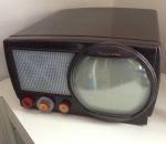
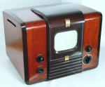
that sets looks as good as it did when brand new!i saw several of these back in the 50s and they never had convergence that close.even new right out of the box!you did a beautiful restoration on this.post more pics

|
|
#138
01-20-2014, 11:45 AM
|
||||
|
||||
|
Trying to obtain "perfect" convergence on these vintage sets will drive you nuts.
You have to know when to walk away. -Steve D.
__________________
Please visit my CT-100, CTC-5, vintage color tv site: http://www.wtv-zone.com/Stevetek/
|
|
#139
01-20-2014, 12:26 PM
|
||||
|
||||
|
Three signs that tell me when the convergence is good enough:
1. After crouching for hours, my back feels like someone stabbed a sword into it. 2. The air is thick with foul language. 3. I hear voices from the other room: "Are you still fiddling with that? We're sitting down to dinner!"  Phil Nelson
|
|
#141
01-21-2014, 01:22 AM
|
||||
|
||||
|
Tom, your work on that CT-100 is fantastic, a real gift to the early television community.
I would not have known that you could disassemble the cabinet and especially the speaker grille that way. Your results give me high hope for improving my own CT-100 in the future.
__________________
Chris Quote from another forum: "(Antique TV collecting) always seemed to me to be a fringe hobby that only weirdos did."
|
|
#142
01-22-2014, 08:56 PM
|
||||
|
||||
|
I've been enjoying watching this set over the past few days, but there was one major shortcoming -- the focus stability. I could adjust the focus for a poor compromise: slightly out of focus for a dark scene, nicely in focus for a medium bright scene, and completely blown-out of focus for a bright scene.
Measurements showed that the problem was not insufficient HV anode voltage regulation, but rather unstable focus voltage. The focus supply is completely unregulated, and unfortunately it seems that the current drawn by the focus grid of the CRT varies quite a bit with scene brightness. Looking at the circuit, I got the idea of using a high voltage zener diode to stabilize the focus voltage: I replaced the resistor below the focus pot with a 3000 volt zener. Or more precisely, a string of 15 Z4KE200A 200 volt 1.5 watt zener diodes. Here are a few pictures: Somewhat to my surprise, this is a fantastic fix. The focus goes from being completely problematic to rock solid. I can turn the brightness and contrast up all the way, to the point the picture looks very bad in other respects, but the focus stays sharp under all circumstances! Now I realize this isn't really "preservation," but given that I have had the experience of seeing how the set works in its original state, I would say I have experienced that enough, and now I'm ready to watch a set that really works. Given that my high voltage cage doesn't look particularly original any more because of the big voltage tripler module, this little insertion of a string of small zener diodes is hardly noticeable, and of course is easily reversible.
|
|
#144
01-22-2014, 10:49 PM
|
||||
|
||||
|
Genius!
__________________
tvontheporch.com
|
|
#145
01-22-2014, 11:51 PM
|
||||
|
||||
|
How creative. May I ask what gave you this idea?
Phil Nelson
|
| Audiokarma |
|
#146
01-23-2014, 12:46 AM
|
||||
|
||||
|
Well, a zener diode is basically the simplest kind of voltage regulation circuit, quite useful when a fairly limited range of current supply is needed. I was curious how high a voltage one could find in a single zener, and generally found that common ones top out at 200 volts. Since they are quite inexpensive, putting a bunch of them in series is still quite cheap, and they don't take up much space.
I've used zener regulation in battery eliminator power supplies I've built for 1920s radios and later tube-type portable radios, so I'm generally familiar with their usage for this purpose. The current in the focus circuit is very low, so not much power dissipation is needed. Using 1.5 watt rated diodes is complete overkill, but there was no real cost difference between these are lower power ones, so I went with these. I also bought some 4 kV rectifier diodes with the idea of putting several in series to replace the 1X2 focus rectifier tube in case that was also needed. But so far, it seems to be fine with the original vacuum tube rectifier, so I'll leave that in there in the interest of keeping as much of the vintage circuitry going as possible. I've done a little more circuitry modification this evening to improve the color tracking from dark to light. Basically, with the condition my CRT is in (which doesn't seem all that bad on the tester, but does show a weaker red gun compare to the other two), I found that it was not possible to adjust the green and blue drive low enough or the green background high enough, if I had the screen settings about right for good grey level color balance. So I modified the range of all those controls, and now the color tracking from black to white is reasonably decent. These changes have slightly hurt the dynamic convergence, so I'll go back and see if that can be improved by readjustment now that the other settings seem to be in the right range. In particular, adjustment of the screen voltages seems to impact convergence (and focus) so it's not surprising that convergence will need some touch up.
|
|
#147
01-23-2014, 06:44 AM
|
||||
|
||||
|
Adjustable high voltage shunt regulators based on a string of zener diodes combined with a totem pole arrangement of bipolar transistors were fairly common in high end display monitor high voltage power supplies throughout the 80's. They were used for the Focus, G2 and G1 outputs, and could be very tightly regulated if used in conjunction with a feedback loop and error amplifier. If I recall correctly, we used 1N5281 zeners and 2N6517 transistors for the Focus and G2 circuits, and 2N6520 transistors for the G1. I used to design them for a living. Great idea for your CT100!
Last edited by hi_volt; 01-23-2014 at 06:50 AM.
|
|
#148
01-23-2014, 05:12 PM
|
||||
|
||||
|
Does anyone know what the original back cover screws looked like on this set? I've got the original back cover, but it was tacked on with just a few dissimilar screws. I'll get a set of something that looks similar to the originals if I can find out what they were.
|
|
#149
01-23-2014, 06:26 PM
|
||||
|
||||
|
Tom,
If you're interested in CT-100 'hot rodding', I dabbled with a few circuit mods that RCA themselves included in later chassis. For starters the vertical oscillator circuit in the CTC-2 gets its plate voltage directly from the LV power supply, where on later chassis it would come from B+boost. This change was necessary in later sets having larger screen sizes, because with the vertical circuit powered from the LV supply changes in horizontal width would not have any influence on vertical height. The result was that on an overly bright scene which might tend to load the horizontal section (really any situation where the potential of the horizontal circuit changed drastically, such as line fluctuations), horizontal width would tend to shrink while vertical remained largely unchanged. This causes the picture to appear somewhat 'squeezed', much like drawing an image on a rubber band or silly putty and stretching it out. Thus with vertical potential directly tied to horizontal the entire picture size would change in a more or less equal way, rather than losing only width and ending up with funny raster geometry. It's really noticeable with a crosshatch on screen, less objectionable with live images. I moved the vertical plate supply to B+boost on my chassis and it works quite well, only other thing I had to change was the value of R144 (Sams) to account for the different supply voltage. Picture size now tracks well regardless of picture content, no more stretchy raster. I don't remember what value I ended up with, I just futzed around with different value resistors till I had something that worked well with the range of the height control. I believe later sets also had the shunt regulator cathode returned to B+boost, rather than B+ or ground. This leads to less voltage across the tube, potentially making it more stable as a circuit but also lessening the stress on it in operation. It's not uncommon for shunt regs to have red plates in operation, but some of them really get hot. Not that 6BD4's are getting scarce or anything, just for the sake of what I will term 'generational improvements' in the chassis. No reason for the CTC-2 to fall behind in other areas, when it was blessed with such great picture quality right? Lastly, I seem to recall the resistors in the shunt reg control circuit had drifted a lot, leading to no real ability to bring HV into it's proper range. After I replaced the out of spec ones, I could now vary HV into the correct range. Great looking set, there's room to be much better! 
__________________
Evolution... 
|
|
#150
01-24-2014, 12:42 AM
|
||||
|
||||
|
Thanks for the tips on possible modification of the vertical deflection power supply. I'll keep an eye out for the type of image squeeze you describe, and fix it if it looks like it's a problem. So far I don't see it, so perhaps that happens more with the larger screen sizes of later sets as you describe.
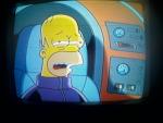
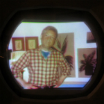
My shunt regulator is working fine, so I won't need to change resistors there. On the other hand, man did this set need a lot of work to get this far. If I was looking for a trial-by-fire set to learn about color TV, this set ended up giving it to me and more. Particularly in the area of alignment it needed many hours of work. And of course all the stuff with the flyback and voltage tripler ended up giving me more education than I necessarily had intended to sign up for! After making some minor modifications to the adjustment ranges of the various color drive, screen, and background control ranges, I gave the convergence some more attention. I was able to get it much better after figuring out that the position and orientation of the yoke has a pretty big impact on convergence (as well as purity, raster scan linearity, and probably a few more things!). After some careful adjustment of yoke position and observing the interaction with the convergence adjustments, I got it looking reasonably decent: No problematic areas left in any part of the screen, although there is just a touch of misconvergence on the left. Mainly I wanted to fix the poor convergence I previously had on the bottom, because that is where text banners often appear, and poor convergence really messes up the fine print. I also found I was able to get the vertical linearity better at the bottom of the screen by replacing the vertical osc/output tube. I think I *might* actually be "mostly done" with electronic restoration. Color fidelity is by no means outstanding, although I'm not sure how good these sets can really be. I know my CRT red gun is a little weak, and that is certainly making it difficult to get good color tracking from black to white. Also, certain colors like orange are never quite right. Nonetheless, it's quite a lot of fun to watch now. I'm probably overdoing it here, but here are a bunch of screen shots off live over-the-air TV this evening: With all the work that has gone into aligning, adjusting, etc., I simply can't imagine that the typical TV sales shop was capable of really doing justice to one of these sets when installing in a customer's home. In New York City or Philadelphia, maybe some RCA factory hot shot set up the sets for customers, but in other places I imagine the skill level of the installation techs was mixed at best. I remember as a kid in the late 60s and early 70s seeing color sets at neighbors' homes that were wildly out of adjustment, and those were sets a lot newer that this that weren't nearly so difficult to adjust. I can only imagine how some of these CT-100s looked in customers' homes in the mid 1950s! Maybe some of you remember those times and can tell me I'm wrong...
|
| Audiokarma |
 |
|
|


 Linear Mode

