
|
|
|
#151
 06-22-2011, 06:47 PM
|
||||
|
||||
|
Dave, thanks for the data, and that is a real shame about the crack in your faceplate.
__________________
John Folsom 
|
|
#152
06-22-2011, 07:12 PM
|
||||
|
||||
|
The museum's 6 bolt, 14 pin tube is paper tagged:
Developmental type - C73293C Serial: L1188 Also on the tag: 1350 I can't find a number stamped on the rim, but my rim is rusted and dented. We also have a single gun developmental tube, paper tagged: Developmental type: C73275 Serial: CR3089-1, DK29217 Also on the tag: H-357 Rim: DT45 In paint on the metal shell: DK29217
|
|
#153
06-22-2011, 07:37 PM
|
||||
|
||||
|
I thought these numbers on the rim of the CRTs were making sense as a serialization number for the shells and therefore the CRTs. All the rim numbers seemed to match up with the likely chronological sequence of the tubes. But Dave's CRT rim number seems out of place. So maybe the rim numbers don't mean much...could be just lot or batch numbers for the bells.
Also, I checked the rim of the 3 bolt 20 pin metal bell prototype in my CBS proto set, and it has no rim number. And the part of the paper tag with the "C" number is missing. But I a certain it the the youngest of the metal bell prototype tube identified so far, due to the 3 bolt faceplate mounting and the fact that the mu-metal shield is an external component. I believe the C73293 and C73547 series tubes had an internal mu-metal shield incorporated into the design. If anyone else knows of any other metal bell prototype CRTs, please get me in touch with the owner. Thanks!
__________________
John Folsom
|
|
#154
06-22-2011, 07:39 PM
|
||||
|
||||
|
John, given the riches I have with my little collection of rare sets, the spare parts I have and all the help I get around here, a small crack is nothing. My minor contributions are more important than a crack. Knowledge is everything.
__________________
Once you eliminate the impossible...whatever remains, no matter how improbable, must be the truth." Sherlock Holmes.
|
|
#155
06-22-2011, 07:45 PM
|
||||
|
||||
|
John, your supposition that the 3 bolt version is the earliest one conflicts with the information that Dave gave me some time ago. Here is what he wrote:
This tube [the 6 bolt version] was use in the tri-color models 1 and 2 and possibly the 2A. Model 1 was the first RCA demo to the FCC. These tubes were circa April, 1950 to February, 1952. Models 3 and 3A used a 3-bolt version. Starting with the 3, they improved the trajectory of the guide bolts for the shadow mask alignment. The model 4 appears to be the first of the glass tubes. Most of what I know can be found in the RCA Color TV submission to the FCC...the "red book"...and in the second "Proceedings of the IRE" on color television.
|
| Audiokarma |
|
#156
06-22-2011, 08:05 PM
|
||||
|
||||
|
I'm under the microscope now. I can stand to be corrected from the dimunition of time. The 6 to 3 does seem to be logical as they improved as does the 14 to 21 pin base.
Perhaps we should start another thread just for these efforts. I would like to know how the mechanics of these seemingly eccentric bolts worked. These are not just locking bolts but perform a function...but what? I am not surprised that RCA had to develop a shadow mask that was moveable for the developmental stage until mfg could catch up with precision. It would take an artist to move these bolts to allignment under the light box used to align the shadow mask as seen in the documentation. You would think that any one bolt could distort the shadow mask not to mention 5 more.
__________________
Once you eliminate the impossible...whatever remains, no matter how improbable, must be the truth." Sherlock Holmes. Last edited by Dave A; 06-22-2011 at 08:50 PM. Reason: text
|
|
#157
06-22-2011, 08:09 PM
|
||||
|
||||
|
John, you are almost always right.
|
|
#158
06-22-2011, 09:06 PM
|
||||
|
||||
|
Uh oops. Poor choice of wording on my part. What I intended to say was the 3 bolt mounting version of the CRT post dates the earlier 6 bolt versions.
__________________
John Folsom
|
|
#159
06-23-2011, 09:53 AM
|
||||
|
||||
|
Quote:
Another wrinkle, then: mine has an external shield, which sits on the plastic (capacitive?) insulator.
__________________
Evolution... 
|
|
#160
06-23-2011, 10:07 AM
|
||||
|
||||
|
In other developments, I believe I have narrowed down the demodulator tubes. They are positioned in a hard to reach area, under the support for the yoke. I wiped away the dirt to find R-Y and B-Y pots.
Also, thanks to John's schematic of his prototype set, I did some looking around on my chassis and believe I have found how dynamic convergence is done. I was apparently incorrect when I told Steve that the only wire connected to the convergence pot wiper is the CRT: looking again, there is a wire leading down to a chassis isolated doorknob cap which then leads into small transformers in the vert and horiz sections. I believe these would be the dynamic transformers, based on the wiring I'm seeing. The numbers on the horizontal transformer are T-6942 and vertical is 208T9 and 274113.
__________________
Evolution...
|
| Audiokarma |
|
#161
06-23-2011, 10:34 AM
|
||||
|
||||
|
Quote:
I believe that last number is a Mfg and Date code, RCA built (274) and 113 would be the 13th week of 1951. The transformer in your last picture has a 274125 number or mid 1951. Are these off the shelf RCA parts or were they made specifically for the Prototype?
|
|
#162
06-23-2011, 11:22 AM
|
||||
|
||||
|
Quote:
__________________
Evolution...
|
|
#163
06-23-2011, 05:14 PM
|
||||
|
||||
|
Nick, I am comforted by your discovery of convergence transformers. :-) BTW, that schematic is from a RCA CRT symposium, not a set I have.
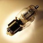
I may be wrong (I often ma) about the mu-metal shield. The C73293 CRTs are shown to have an internal mu-metal shield. I don't have and explicit data on the C73547 CRTs, but the one in my Sparton also has a external mu-metal shield, so this would seem to indicate the C73547 series tubes use an external shield. Attached is an assembly drawing of the C73293 series tube.
__________________
John Folsom
|
|
#164
06-23-2011, 05:49 PM
|
||||
|
||||
|
History of CPA
I have been reading some interesting IEEE articles on early CPA. An especially interesting one is by Bernard Loughlin who worked for Hazeltine Labs in the early 50's. He presented a paper at the Seventh Chicago Spring conference on Broadcast and Television receivers in Chicago in 1966 on the PAL TV system. He makes reference to the early CPA and he puts CPA in the context of what later transpired with the evolution of world standards.
CPA or color phase alternation appears to have originated to help offset the problem of limited bandwidth of the RMA US TV channel eg 6MHz. It is interesting to think that 6MHz is still with us for the ATSC system. But it seems that by the early 50's, after the constant luminance with restricted bandwidth chroma channels has been accepted that somehow interleaving the chroma with he luma as cleanly as possible was the ultimate challenge. The original NTSC CPA approach was to vestigially modulate B-Y and R-Y with a subcarrier of 3.89 MHz and phase alternate B-Y at either field rate or line rate. (Europe ultimately chose alternating R-Y at line rate). The vestigial sideband approach was to extend the chroma bandwidth and the B-Y alternation would minimize quadrature crosstalk between R-Y and B-Y. It appears of the two options, the 1952 field test used field alternation rather than line alternation. Is this correct? Slight phase errors would introduce flicker on image edges or chroma transitions due to the crosstalk not being properly integrated or cancelled. It appears that in 1952, a one line delay line was impractically expensive for consumer use and so the true benefit of CPA Phase Alternate Line had to wait a decade and a half. It appears that the failure of the 1952 CPA test was due to color subcarrier to sound carrier beats (600kHz) and vestigial sideband quadrature crosstalk. Lowering the subcarrier to 3.58MHz and the IQ working overcame the most of the problems. With regards to the prototype, it appears that if it is indeed still configured for 1952 field CPA, the conversion to IQ NTSC should be relatively straight forward. The crystal frequency of 3.89MHz should indicate whether it is remains the CPA prototype. Chroma demodulation would be restricted to equal band R-Y/ B-Y demodulation since there is no bandwidth differentiation between I and Q in the original CPA prototype. That is, unless it was later further modified.
|
|
#165
06-23-2011, 06:17 PM
|
||||
|
||||
|
Glad to hear you found the convergence circuitry. Now it makes sense. The next mystery is to figure out what color scheme it uses.
|
| Audiokarma |
 |
|
|


 Linear Mode

