#1
|
||||
|
||||
Attention Old Coot Gotham Needs Your Help
I feel like I should have a "Bat Signal" to shoot up in the sky to alert Bill. Maybe it could be in the shape of a soldering iron or a 10BP4 .
I have another head scratcher that I have been working through for a couple of weeks and I'm out of ideas. I am working on the television chassis on a 730TV1 and I have something bogging down my B+ supply. It sort of feels like deja vu as I just had this problem not long ago on another set. That one was much easier to go through and figure out where the problem was created, this set is stumping me completely. Here is the whole schematic for reference http://www.earlytelevision.org/pdf/R...-Sams-70-7.pdf I have taken a shot of the section below where I can isolate and remove the problem. This section is just past the main filter capacitors (and choke) on the B+ supply. If I remove BOTH positive leads on C4 my B+ supply is healthy. If, however, I connect EITHER positive lead on C4 my B+ drops to right around 90V. I have temporarily swapped in two replacement caps for C4 and it makes no change. I have removed the wiper leads on R5 and R6 to isolate the yoke and there is no change. I'm at the end of my current skill set. What am I missing?
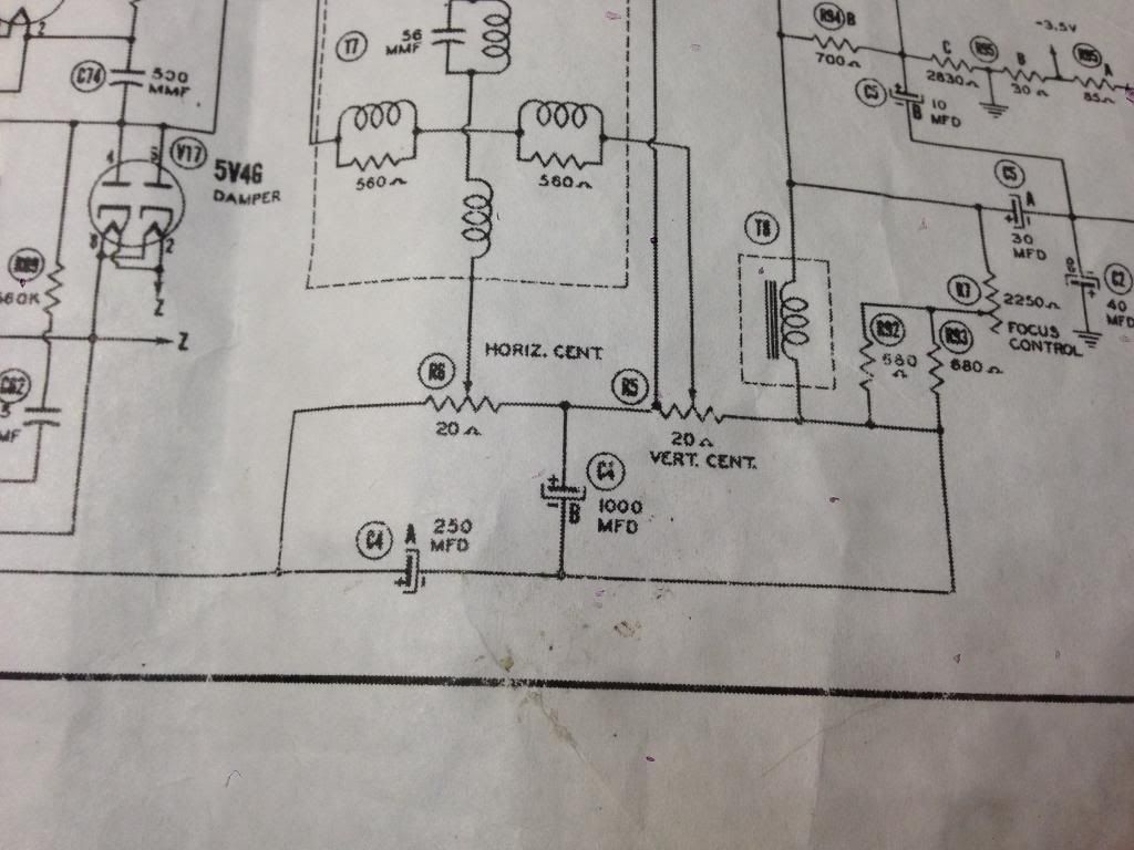
__________________
John |
#2
|
||||
|
||||
I took a poke at the schematic, and I am also scratching my head. The fact that the voltage droops to that extent usually means something upstream is severely limiting the current, but the only thing I can see "upstream" aside from the choke would be a weak 5U4G rectifier, also possibly one side of the line transformer may be disconnected or open, since if you were to try to pull full current over a half-functioning rectifier in that configuration you'd get somewhere around 90v and a whole boatload of ripple. Can you hook a scope up to the B+ line and examine it unloaded and loaded (without and with the caps). If it gets all wiggly when you load it then I could be on the right track.
Easiest thing though is pull the rectifier and confirm you have both sides of the B+ winding present and functioning, then scrutinize the rectifier itself. Hope this helps, or at least gives you a few new trees to bark up. |
#3
|
|||
|
|||
Um.. for starters, look for an open in the chain of back-bias resistors (R94, R95A/B, R96).
Since these go from center tap of the HV secondary to ground, an open would cause loss of B+. |
#4
|
||||
|
||||
Sadly neither one of your theories are correct. The voltage dividers are all on spec thankfully as those are almost always bad.
__________________
John |
#5
|
|||
|
|||
Hokay. So.. with the set off, check resistance from c.t. of the HV winding to ground. It should be no higher than the sum of those three resistors (R94, R95A/B, R96).
If good, check HV winding continuity from c.t. to plates of the rectifier (pins 4 and 6). If good, turn the set on and measure voltage across C1A and C2A. It should be the full B+ voltage (minus the drop across the R94/R95A-B/R96 chain). The top of that chain should be around -85V, as it is the negative supply source. B+ should also appear on C3A, on the downstream side of the choke. |
Audiokarma |
#6
|
||||
|
||||
Quote:
Quote:
Quote:
Quote:
__________________
John |
#7
|
||||
|
||||
Could the pots have bad tin whiskers shorting the terminals to the case?
__________________
Tom C. Zenith: The quality stays in EVEN after the name falls off! What I want. --> http://www.videokarma.org/showpost.p...62&postcount=4 |
#8
|
|||
|
|||
Dang, this'n is a brain buster for sure. Nothing about the symptoms make any sense unless... and this is purely a shot in the dark:
Those replacement caps for C4A and C4B. Sometimes foreign-sourced electrolytics have the arrow pointing to the negative end of the cap. Intuitively, you'd think the arrow should point to the positive end, and you end up installing the cap backwards. Is there any chance that coulda happened? Another shot in the dark.. are you using a digital meter to take voltage readings? If so, is there any chance you could use an analog meter to re-take the readings? I would never trust a digital meter on anything other than pure DC or pure sine wave AC. |
#9
|
||||
|
||||
Bingo. Focus coil wiper to ground. That'll catch you every time. Hidden little sucker too.
__________________
John |
#10
|
|||
|
|||
Wow, congradumalations.
Looks like "do a preemptive sweep for tin whiskers" should be added to one's service repertoire whenever encountering a weird problem in a vintage set. |
Audiokarma |
#11
|
||||
|
||||
Definitely added to the list especially since this is the second set with that problem.
__________________
John |
#12
|
|||
|
|||
Yeah, IIRC there was another member (Geist?) who had an early RCA with a mystery short that cleared itself, with tin whisker the suspected cause.
I've yet to add it my "check for this first" mental file. |
#13
|
||||
|
||||
That whisker must have been drawing quite a bit of current to load down the B+ that much, I'm surprised that there there was no smoke or fireworks to reveal the location of the short.
jr |
#14
|
||||
|
||||
It was actually a "splatter" of solder that was the culprit. I didn't leave the set powered on for more than 10 seconds or so while I was experiencing the problem so it wouldn't have had enough time to heat up to smoke stage.
__________________
John |
#15
|
|||
|
|||
What had me bamboozled was the absence of overheating or any indication of excessive current being drawn from the B+ supply. In fact only half the normal voltage was appearing across the resistor chain (R94/R95/R96), indicating only half the normal current was being drawn (total supply current flows thru that chain).
Anyhow, glad U got it sorted out. Last edited by old_coot88; 05-06-2015 at 05:07 PM. |
Audiokarma |
|
|