
|
|
|
#226
 06-29-2017, 08:06 PM
|
||||
|
||||
|
Quote:
__________________
 Admiral C322C2 Regent (Restoring) RCA CTC-7 Pensbury (Restored) RCA CTC-5 Westcott (Restored) CRA CTC--4 Director 21 (Restoring) 
|
|
#227
06-29-2017, 09:27 PM
|
||||
|
||||
|
Quote:
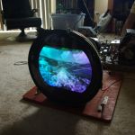
Executive summary: video injection requires adding a video preamp as described in the 1956 RCA Broadcast News article. I did breadboard such a preamp, but version 1.0 was disappointing and I set the project aside to work on other stuff for a while. On the positive side, those are pretty true-looking color bars. You are not far from having a very watchable CTC-4. The edge convergence might never be as good as the center convergence, but that's common in early color roundies. Whichever manual you follow, take Bill's advice -- go step by step in the order shown and do not skip steps. Phil Nelson Phil's Old Radios http://antiqueradio.org/index.html
|
|
#228
06-29-2017, 09:32 PM
|
||||
|
||||
|
This is the best I can get on height and linearity. As you can see the height isnt quite high enough. I swapped vertical out tubes with a bit of improvement. Hmmm, usually insufficient vertical height would indicate bad filters maybe, but all have been replaced so it must be something else.
__________________
Admiral C322C2 Regent (Restoring) RCA CTC-7 Pensbury (Restored) RCA CTC-5 Westcott (Restored) CRA CTC--4 Director 21 (Restoring)
|
|
#229
06-30-2017, 11:12 AM
|
||||
|
||||
|
Quote:
__________________
Admiral C322C2 Regent (Restoring) RCA CTC-7 Pensbury (Restored) RCA CTC-5 Westcott (Restored) CRA CTC--4 Director 21 (Restoring)
|
|
#230
06-30-2017, 01:44 PM
|
||||
|
||||
|
I will be out of town for the 4th until next Wednesday. While I am gone, I will do some reading through the manuals and gather some extra info on the problem areas. Until then stay tuned! Everyone have a happy 4th of July and I'll be back on this set next week!

__________________
Admiral C322C2 Regent (Restoring) RCA CTC-7 Pensbury (Restored) RCA CTC-5 Westcott (Restored) CRA CTC--4 Director 21 (Restoring)
|
| Audiokarma |
|
#231
06-30-2017, 08:56 PM
|
|||
|
|||
|
You likely have some bad capacitors in the vertical stage still. If you could put a circle pattern up from a generator or dvd, you can adjust for a perfect circle then you will see if the raster will fill the screen. Also check the circuit grounds in the vertical output stage. B+ could be a little low. If it is to low the picture will usually pull in horizontally some. Be sure and check the resistors as well. There may be some that have drifted high in value.
|
|
#232
07-08-2017, 04:34 PM
|
||||
|
||||
|
After leaving no stone unturned in the vertical circuit (which isnt many). I found only one barely out of tolerance resistor a 2.2meg 1/2w coming off G1 of the 6AQ5 vertical amp then goes to ground. Not sure it is too critical and its just barely off spec I mean like less than 1% off spec so I might just leave it. All caps are fine except I did replace a .039 which comes off the plate of the vertical amp and goes to the red cathode of the CRT. The original the maroon drop cap tested OK but I had a cap on hand and replaced it. Dont think it will make the vertical any higher though..
__________________
Admiral C322C2 Regent (Restoring) RCA CTC-7 Pensbury (Restored) RCA CTC-5 Westcott (Restored) CRA CTC--4 Director 21 (Restoring)
|
|
#233
07-08-2017, 07:23 PM
|
|||
|
|||
|
Quote:
|
|
#234
07-09-2017, 10:00 AM
|
||||
|
||||
|
Lack of height is nearly always drifted dropping resistors coming from B+boost so look at R119, the height pot, R117 and R118. If they all spec out, lower the value of R119 till the picture fills the screen. If I had to guess our vertical output transformers are going soft slowly, only solution is to feed them more voltage. Those are Sams resistors BTW.
__________________
Evolution... 
|
|
#235
07-09-2017, 04:57 PM
|
||||
|
||||
|
Quote:
__________________
Admiral C322C2 Regent (Restoring) RCA CTC-7 Pensbury (Restored) RCA CTC-5 Westcott (Restored) CRA CTC--4 Director 21 (Restoring)
|
| Audiokarma |
|
#236
07-09-2017, 07:20 PM
|
||||
|
||||
|
Hmm... can you measure the high voltage? If it's high, it may reduce the scan size.
Also, if you have a variac, try adjusting the line voltage.
|
|
#237
07-10-2017, 11:57 AM
|
||||
|
||||
|
Quote:
__________________
Admiral C322C2 Regent (Restoring) RCA CTC-7 Pensbury (Restored) RCA CTC-5 Westcott (Restored) CRA CTC--4 Director 21 (Restoring)
|
|
#238
07-10-2017, 04:36 PM
|
||||
|
||||
|
Great, now I have even less height and now fold over!
 Looks like I need to retrace my steps here. All I did was replace a cap. I did clip the leg of a few resistors and soldered them back in. I will start by checking my connections on the resistors and cap. Looks like I need to retrace my steps here. All I did was replace a cap. I did clip the leg of a few resistors and soldered them back in. I will start by checking my connections on the resistors and cap.
__________________
Admiral C322C2 Regent (Restoring) RCA CTC-7 Pensbury (Restored) RCA CTC-5 Westcott (Restored) CRA CTC--4 Director 21 (Restoring)
|
|
#239
07-10-2017, 08:04 PM
|
|||
|
|||
|
I would run the vert. hold stop-to-stop before diving into it again. It may be locking at an odd sweep rate.
Also, on the line voltage issue, measure the heater voltage. If it's running signifigantly above or below the nominal 6.3 VAC, it'll tell you whether the line voltage is kosher or not. Last edited by old_coot88; 07-10-2017 at 08:13 PM.
|
|
#240
07-10-2017, 08:12 PM
|
||||
|
||||
|
Quote:
__________________
Admiral C322C2 Regent (Restoring) RCA CTC-7 Pensbury (Restored) RCA CTC-5 Westcott (Restored) CRA CTC--4 Director 21 (Restoring)
|
| Audiokarma |
 |
| Thread Tools | |
| Display Modes | |
|
|


 Linear Mode

