
|
|
|
#91
 11-24-2017, 05:21 PM
|
|||
|
|||
|
Glad to hear that. All the best with your restorations.

|
|
#92
11-24-2017, 05:44 PM
|
|||
|
|||
|
On to the turret. This turret is massive and very well built. First a photo 'walk around".
Here it is just removed from the chassis with the outboard cover removed.  The aft (motor driven end), if so equipped.  Looking at the side that faces to picture tube.  This is the side that faces forward. It also has the oscillator adjustment tool and drive gear.  Close up of the front end.  A close up of the detent mechanism. Another indication of the quality of this TV.  The aft end ball race adjuster. The turret is suspended by 2 ball bearings. The front end uses a race and 9 "free range" ball bearings, while the aft end uses a thrust bearing. The aft end race can be adjusted in or out to get all the "play" out yet still spin freely.  The front end race.  The aft thrust bearing and the 9 balls for the front race.  A close up of the front shaft where the balls ride.  A close up of the aft section where the thrust bearing rides.  I took this picture to "locate" the actual strip according to the number stamped into the turret. 
|
|
#93
11-24-2017, 06:00 PM
|
|||
|
|||
|
I removed each strip and then I cleaned all the parts and removed some light rust from the inside of the cage. The strips will be dealt with later.
The turret is copper plated steel and while cleaning and polishing it, I rubbed through the plating. My idea was to clear coat the polished copper plated turret to prevent it from tarnishing. Then I remembered that I had some Rust-Oleum Metalic Copper spray paint. A couple of quick coats and we are in business. Here is a picture of the aft end where I masked off the thrust bearing race and the new paint. Not much difference. The turret looks very good painted.  Here is a picture of the turret installed into the cage and the free end play adjusted along with the drive gear installed. The turret spins very nicely with no end play.  The end play is taken up by screwing in on the aft ball race. When adjusted just right, the large nut is then tightened to "lock" the assembly. While this might lock the assembly, there was some greenish looking liquid applied to the lock nut and race to prevent it from coming loose. I used some Super Corona Dope that I had to lock the assembly down.  A close up of the front end after assembly. 
|
|
#94
11-25-2017, 11:05 AM
|
|||
|
|||
|
Next up, the tuning strips. There are 12 strips in all. Channels 2 thru 13. On the turret there are 13 spots for strips. One of them is left blank. Perhaps the blank position was forward looking for a UHF converter.
Each strip has some coils and capacitors. No resistors.   I cleaned the fingers using contact cleaner and an acid brush cut down to about 3/8 inch.    After they were cleaned, I used some De-Oxit and a Q-Tip and swabbed each side of each finger. I also marked on the bottom side the channel number.
|
|
#95
11-25-2017, 11:15 AM
|
||||
|
||||
|
UHF channel strips were available for these tuners and IIRC were more common than UHF converters/outboard tuners with these sets. Watch a youtube video of an old Zenith film 'Fog Over Portland' for an interesting look at Zenith's UHF preparations.
__________________
Tom C. Zenith: The quality stays in EVEN after the name falls off! What I want. --> http://www.videokarma.org/showpost.p...62&postcount=4
|
| Audiokarma |
|
#96
11-25-2017, 03:25 PM
|
|||
|
|||
|
Quote:
|
|
#97
11-25-2017, 03:42 PM
|
|||
|
|||
|
Let's get those strips mounted and the assembly installed.
I mounted the cage to the main chassis and installed the "idler" gear. The idler gear was lubricated and bolted to the bracket, which was then screwed to the cage.  I then soldered on the wires removed when taking off the tuner assembly. Then the tuner was installed on top of the cage using the witness marks left when originally installed. I then screwed the first strip in place using the 2 4-40 screws and lock washers. I then carefully lined up the strip to the tuner and tightened the strip screws. This was repeated for all the rest of the strips.   I then carefully rotated the turret and could hear some fingers clicking rather than a nice wiping sound. There were 3 strips that made this noise. After careful examination I could see that these 3 strips were bowed up in the middle. I then bent the mounting ears on the turret down just a little bit using an adjustable wrench.  Remounted the strips and the problem was solved. I had a nice wiping sound on all the strips. I then applied some DE-Oxit to each side of each finger on each strip, then ran it through the tuner contacts. I did this twice to be sure I had clean contacts. I then installed the cover to protect those strips.
|
|
#98
11-25-2017, 03:49 PM
|
|||
|
|||
|
The tuning shaft was the next item to be installed. I lubed the end that was nearest to the gear, and the channel selector knob shaft as it passed through the front of the chassis.
  I then aligned the turret with the channel selector by rotating the gear that attaches to the turret. I then tightened all the set screws and very lightly lubed the gears.
|
|
#99
11-25-2017, 05:13 PM
|
|||
|
|||
|
I installed the fly back and HV cage. No issues.
 
|
|
#100
11-26-2017, 07:48 PM
|
|||
|
|||
|
I replaced the 2 560 ohm yoke resistors and the 56pf 1Kv cap. I used a 56pf 3Kv COG disc cap. None of these 3 components were listed in the Sams parts lists but were listed in Riders.
 
Last edited by Crist Rigott; 11-26-2017 at 08:54 PM.
|
| Audiokarma |
|
#101
11-26-2017, 08:56 PM
|
|||
|
|||
|
Tomorrow I should be able to attach the yoke and focus coil wires. Then do my resistance check. Then if all is good, then the first power up.
|
|
#102
11-27-2017, 01:00 PM
|
||||
|
||||
|
Looking great! I wish I had your patience!
Just curious... what is the ch number sequence of the strip placement and the ch number sequence of the indicator dial. From what I can see in the pix, it looks like the indicator dial is in numerical order but the strips are placed in a "most likely sequence for a given area" order. Scratching my head over how that works.  jr
|
|
#103
11-28-2017, 08:14 PM
|
|||
|
|||
|
Quote:
|
|
#104
11-28-2017, 08:23 PM
|
|||
|
|||
|
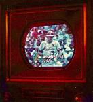
The resistance check so no errors.
I then powered it up with the rectifier tubes out. The filaments all glowed nicely. Then rectifier tubes in and I got B+ voltages. The high B+ reads 328V vs 360V and the lower B+ reads 186V vs 130v.  I have 11.5Kv and the picture looks washed out. All I've done so far is adjust the front controls. V Lin, V Size, Bright, Contrast, H Hold, V Hold, and the Buzz control on the back.  https://youtu.be/1U6SL5BV6-Y Any idea as to where to start? BTW, the test CRT is an 8YP4 with the adapter harness.
|
|
#105
11-28-2017, 09:23 PM
|
|||
|
|||
|
Possibly an open peaking coil in the video chain, somewhere 'upstream' of the sync take off point.
|
| Audiokarma |
 |
|
|


 Linear Mode

