
|
|
|
#1
 08-07-2015, 12:06 AM
|
||||
|
||||
|
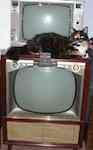
Zenith C845
The only thing wrong with this radio as I found it was a tube with an open filament (one of the IFs). But I recapped it anyway, as I plan on using it regularly as my basement radio. This is a really impressive radio. It's the most sensitive (on FM) table radio I've ever had, it's not bad on AM, and it's the best sounding table radio I've ever had by far (It has an 8" speaker, and a tweeter).
Last edited by Adam; 12-27-2017 at 01:45 PM. 
|
|
#3
08-07-2015, 10:31 AM
|
||||
|
||||
|
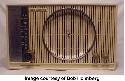
I got one 2. FM is balls out design. Uses a PTO "permability tuned
oscillator". Instead of tuning a cap it tunes coils. The cap is for AM & you can see the coils for FM beside it. Nobody else built so high a quality table radio. You will enjoy it for the rest of your life & then some. 73 Zeno
|
|
#4
08-11-2015, 10:52 PM
|
||||
|
||||
|
I used to have a Stromberg Carlson console that had a tuner that tuned coils like that. It was also unusually sensitive. I should try this Zenith upstairs. There is so much interference on AM when I try to get it in the basement, it probably works better on AM than I think. And I usually touch up the alignment on table radios, but this one worked so well to begin with, I didn't mess with it at all.
|
|
#5
08-12-2015, 11:24 AM
|
||||
|
||||
|
I also have a C845 (identical to the one in my avatar) which works extremely well. The sound, as Adam pointed out, is excellent, owing to the 2-speaker sound system, as is the FM sensitivity (I can get stations from Erie, Pennsylvania, Detroit, Toledo, Ohio, et al., as well as most every Cleveland FM, just using the built-in FM antenna when the band is open in the summer). I don't know how good the AM reception on my set could be, as the noise level in my apartment is very high (I often get noise between stations that sounds like TV horizontal oscillator harmonics; there is at least one person in my building who still has a CRT TV on a cable box which she watches a lot, but there could be others besides).
The C845 was probably, IMO, one of the best AM-FM table radios Zenith ever made. The C845 was the first version, followed by the C845L and C845M. The differences are slight, mostly in cabinet styling and the addition of a dial light in one of the later versions. The cabinet, so I read a while ago online, was in one of two finishes, either what has been described as "toasted mahogany" or standard mahogany. The toasted mahogany finish can be removed, revealing the true mahogany underneath; however, since my '845 is on top of a chest of drawers in my bedroom in a maple finish, I decided to leave the finish as-is on the radio since it matches the finish on the chest almost perfectly.
__________________
Jeff, WB8NHV Collecting, restoring and enjoying vintage Zenith radios since 2002 Zenith. Gone, but not forgotten.
|
| Audiokarma |
|
#6
08-13-2015, 02:00 PM
|
||||
|
||||
|
The C845 might have been the first Zenith "Interlude" model but I have an H845 dated 1961 that is identical.
The one problem I have had to address on it was a worn-out bandswitch. I carefully cleaned and then re-tensioned the contacts using a chopstick. I found another of the same model on the "free" table at an Antique Radio swap meet. I soon found out why; It had dreaded silvermica disease. http://videokarma.org/showthread.php?t=254601
__________________
"When resistors increase in value, they're worthless" -Dave G
|
|
#7
08-13-2015, 04:12 PM
|
||||
|
||||
|
I have a Zenith like this. and I did this when I replaced the selenium rectifier.
 Full wave rectification, less power supply hum (120Hz vs 60Hz). The heater string runs directly off the powerline (via power switch). The mid point of the heater string will look to have minimal AC waveform in reference to the B- line of the bridge rectifier. But will have a DC bias of about half the B+ voltage. This is fine, cathodes like their heaters to have a positive bias. One end of the audio output tube (for example a 50C5) (#8 in the diagram) heater is probably already connected to one of the AC lines. Disconnect the heater line of the other audio output heater pin. This line, now disconnected (feeding to tube #7), now will be connected to the other AC line. See diagram. And at the old ground end of the heater string, usually the AM or FM detector/ audio driver tube (#1) (19T8 for example) disconnect from ground and connect to the now loose end of the audio output tube heater. This should minimize hum pickup from the heater line. A small cap of around 0.1uF 400V or more tied close to the heater string midpoint should help reduce the AC waveform some more by holding a bias charge between the heater string and the B- ground of the radio during the time the bridge rectifier isn't conducting. The bridge diodes only conduct at the peaks of the AC powerline waveform. Pay special attention to the AC line lead dress around the volume control power switch for hum pickup. Hot chassis radios usually switched the local ground feed line to avoid hum pickup from 120VAC to local ground wires. This could ruin the advantage of full wave rectification (less hum, 120Hz vs 60Hz) if not taken care of. Look for trouble by listening to silent passages in radio programming with the volume control at half setting (hum pickup can be more severe at this position). Shielding may be needed.
__________________

|
|
#8
08-21-2015, 05:36 PM
|
||||
|
||||
|
I've been busy the past week, but now that I finally have some time to think about this … I know how the bridge rectifier works: that when the AC flows in one direction it goes through one pair of diodes, the opposite direction it goes through the other pair of diodes, and you get a full-wave rectifier instead of just half. I see that that .1 uF cap would filter the AC on the heater string. But I don't understand where the DC on the heater string comes from, or how the amount of AC vs DC voltage on the heater line changes with the tube position. (I would think that the total voltage drop across each tube would depend only on the resistance the filament, and would not change if its position were changed)
Last edited by Adam; 08-21-2015 at 05:40 PM.
|
|
#9
08-22-2015, 07:43 AM
|
||||
|
||||
|
I have three Zenith Super Interludes, but they're all H845's (which seem to be the same except for adding dial lights and a darker colored dial background to make the numbers easier to read). All three are excellent performing sets, very dependable, and sound fantastic.
On all three of mine I replaced the selenium rectifiers with a single diode and added a resistor to drop the voltage back down to normal. Simple and easy, and there is no hum whatsoever. The only one of my three that acts up some is the one I use the most at the office. It seems to have an AFC issue, and has to be re-tuned quite often in FM. Once it's on for a few hours, it seems to be better.
|
|
#10
08-22-2015, 02:34 PM
|
||||
|
||||
|
Quote:
You wouldn't be able to draw much current off the heater string "centertap", but in this application, you don't need to.
__________________
|
| Audiokarma |
|
#12
08-22-2015, 03:41 PM
|
||||
|
||||
|
So what's important is the difference in voltage from a given point in the heater string in reference to the B- (not so much the value of the actual voltage drop across the tube). And at the voltage-midpoint of the heater string, this will at most reach 1/2 the value it reaches on the ends. So 6V tube will have a 6V drop across it no matter where in the string it is, but if you measure AC voltage from one end of the heater of the tube to the B-, it will be greater if the tube is towards one edge of the string than towards the middle, and the increase in that voltage difference would be the cause of greater hum.
It sounds great with just the one 1N4007 I have in there, but I'm tempted to try this and see what happens. Maybe over winter break, as I'm running out of free time as the summer is coming to an end. I want to take it apart again anyway to touch up the alignment and see if I can improve the sensitivity on AM. Last edited by Adam; 08-23-2015 at 02:37 PM.
|
 |
| Thread Tools | |
| Display Modes | |
|
|


 Linear Mode

