
|
|
|
#16
 10-04-2012, 04:34 PM
|
|||
|
|||
|
'Scuse the dumb question, but is the 5Y3 filament lighting up?

|
|
#17
10-04-2012, 06:50 PM
|
||||
|
||||
|
I'd like to just say, "um-m, nevermind." But to take full credit--yes, the filament lights...and I just misread the instructions and was looking for 275 V across the filament instead of 5 VAC. Now I'll go back and look for the horizontal size and see if I can find out what smell like it's burning before my wife walks by and asks, "Are you burning something?"
Thanks much. Winky.
|
|
#18
10-04-2012, 08:28 PM
|
||||
|
||||
|
Speaking of horizontal, weren't you going to replace a mica cap or two in that area (C37, C39, perhaps)? Or maybe that has already been done . . . .
Phil Nelson
|
|
#19
10-09-2012, 08:48 PM
|
||||
|
||||
|
Just One More Thing...
I got to the point where all my "fixing" was just introducing new errors, so I walked away from the project for a few days. In fact, I was going to drop this project and move on to something else, but, "As soon as I think I'm out, it pulls me back in." I can always find one more thing to try.
Yes, (Phil) I did try replacing those mica caps. Due to an unfortunate lapse of attention, I forgot they were 1KV caps and I replaced them with 630V caps. That's how I burned up the horizontal size pot. I have since replaced both the caps and the pot. Then I made one last change in the wiring. My set, Phil's recently restored 19A1, and the Sams 19A1 photo all show this connection to the horizontal size pot, so I left it like that even though it didn't agree with my 17T1 schematic.  That's how it is in the Sams schematic, but the Wallace and Riders schematics are different, so I rewired it according to the Wallace 17T1 schematic.  The outcome didn't change much even though I imagine I can see a better image. It still comes up short on horizontal size.  I think I'm done replacing caps and resistors and I've rewired to entirely conform with the schematic. Now I have to ask about the significance of these voltage readings (actual voltage in red). My last bit of rewiring from the sync amp plate (pin 2) reduced the voltage from 125V to 77V. I have no idea if the voltage variance from the HV rectifier (corona ring) to pin 5 on the HV oscillator means anything at all.  Anyone have a clue what could be doing bad things to the horizontal hold and horizontal size? Here's a link to the full schematic: https://picasaweb.google.com/lh/phot...eat=directlink Is it time to put this set back on the shelf? Thanks for your attention. - Winky
|
|
#20
10-09-2012, 09:12 PM
|
||||
|
||||
|
I'd check the resistors and caps and coils between the first 6SN7 triode V11A (of the diagram in your post) and the video amplifier tube. The sync signal may be getting lost or too weak between these tubes.
__________________

|
| Audiokarma |
|
#21
10-09-2012, 11:27 PM
|
||||
|
||||
|
Examining the sync may be worthwhile. Your most recent photos look like you have both vertical and horizontal problems. The image is repeated horizontally (wrong frequency) and the vertical looks stretched out, with too much space between lines.
Compare this photo of my RCA 721TCS at a point when I was partly done recapping. 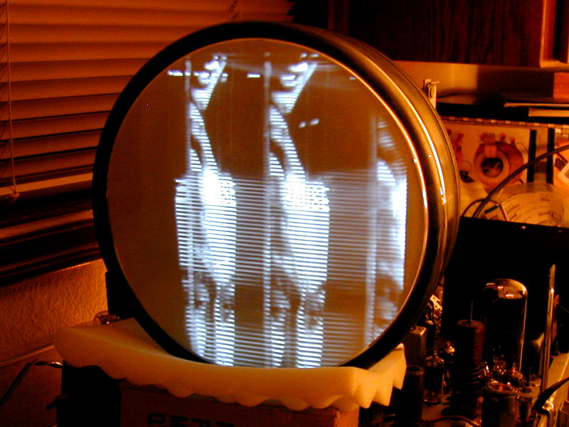 That case also showed the image repeated horizontally, with the images stretched too far vertically. Notice how much space there is between scan lines. The sync section affects both vertical and horizontal, so it may be a logical place to start, as wa2ise suggested. Phil Nelson
|
|
#22
10-10-2012, 12:52 AM
|
||||
|
||||
|
Thanks. I'm working on it.
- Winky
|
|
#23
10-15-2012, 11:34 PM
|
||||
|
||||
|
I'm back.
As advised, I've checked every cap, resistor, and coil from the sync separator through the horizontal and vertical output. I also replaced several mica caps just because I had no way to test them. Everything there seemed to be OK, so I continued the testing back through the video amp and video detector and found one peaking coil to be defective.
 If you look close, you might see what the problem is:  I don't think that has anything to do with my horizontal/vertical sync problem, but I'll fix it anyway. The resistor looks to be 50% too high, so I'll replace it as well. It's a 516 uH coil, and Mouser a 510 uH axial rated for max 124 mA (is that enough for this application?). I managed to get my meter leads across the coil, and it's still about 16 ohms, so I'll attempt to repair it. I only have about 1 millimeter of coil lead to work with, and it's very fine--maybe 600 gauge. I have an idea how to do this, but does anyone have suggestions on microsoldering?  Back to the horizontal/vertical sync: I picked another couple of used 6SN7's, and I'll switch them out just to see if it makes any difference. My understanding of the electronics doesn't go much beyond replacing components, so I hired a gnome to help me out.  He tells me that the sync amp inverts the signal to correct polarity. Could polarity or out-of-phase error cause my kind of problems? The gnome seems to know what he's talking about, but he hasn't shown me any credentials.
|
|
#24
10-16-2012, 01:17 AM
|
||||
|
||||
|
Video output is not your major problem, but as long as you found this bad coil, you may as well deal with it.
I am not an expert on soldering very fine wires, but I have succeeded with caveman technique a couple of times. Sacrifice an old cable like a microphone or headphone cable that has very fine stranded wire for shielding or whatever. Use one strand to bridge between those stubs. Wrap each end of the bridging wire a few times around the stubs using a tweezer or jewelry pliers. Don't heat the joints any longer than needed to flow the solder. It may not be beautiful and it won't survive a hard yank, but if you can make a secure connection between those stubs, it should work. I wouldn't worry about insulation until you know whether it works. Later on, you can dab some liquid tape or corona dope on the bare wire, if you like. Re the horizontal/vertical problems, previously, I puzzled over the modifications done by your previous owner and didn't really see what he was driving at. (Who knows, maybe he didn't, either.) When someone has done modifications or made oddball repairs, there's always the possibility that he did one more Weird Thing you haven't yet noticed. You have a reasonably bright image (thus, some HV and not-too-awful video output). A signal is getting through the RF and IF stages. You have vertical and horizontal deflection. But both the vertical & horizontal sweep are out of whack, so either you have two problems, one in each sweep section, or possibly one problem in the sync stage that feeds both of them. This should not be that hard. Some test instruments (oscilloscope, generator that can supply horizontal & vertical drive signals) would simplify debugging, but that's empty advice if you don't have such gizmos. Yo, smart people -- any ideas? Phil Nelson
|
|
#25
10-18-2012, 01:28 AM
|
||||
|
||||
|
This Project Goes Back on the Shelf
I've done everything within my capabilities for the Admiral 17T12, so it goes back on the shelf until I gain some sophistication in technique and equipment.
In the meantime, I'll get back to the Atwater Kent Model 37. Just for grins and giggles, I repaired the broken peaking coil. It took a couple of hours, but I saved the $1.75 I would have had to pay for a new inductor from Mouser.    Added 33K resistor parallel to get resistance, now 12K, close to the specified value of 8.2K.  Sincere thanks to everyone who helped me with the Admiral. Even though it's not yet a success, it's been fun. If anyone is driving through Boise and happens to have an oscilloscope and a generator in the back seat, please give me a call. - Winky
|
| Audiokarma |
|
#26
10-18-2012, 01:45 AM
|
|||
|
|||
|
Winky Dink,
I am working on a 19a1 set and had the exact same screen you had. I could get a 3 inch wide image with careful adjustment but anything else caused it to break up horizontally and then it looked like yours. Turned out these sets are sensitive to the type of 6sn7 you put in. Mine doesn't like the two new testing GE 6sn7GTB's it had. 2 old used 6sn7GTs made the sweep work fine. Also, if you want to test the horizontal sweep circuit without the sync components there is a cap that goes across V12. It is labelled as C35 and goes across pins 2 and 4. If you disconnect this cap you will let the horizontal run free (no interference from the sync circuit). This should result in a full horizontal sweep that you can momentarily sync using the horizontal hold. It would be a good way to make sure that the horizontal circuit is working OK without the sync input. Hope this helps.
|
|
#27
10-18-2012, 01:49 AM
|
|||
|
|||
|
Did you ever check the resistance on the T3 blocking transformer? You have to lift (and I recommend replacing) the resistors. This transformer and C36 (double check that it is .01) seem to set the basic frequency of the horizontal circuit.
After I changed all the resistors in the horizontal circuit (there are only 3 or 4 fixed resistors) the horizontal hold and size are nicely centered.
|
|
#28
10-18-2012, 09:45 AM
|
||||
|
||||
|
How do the voltages and resistances check out? That could quickly highlight areas of failure and monkeywork.
|
|
#29
10-18-2012, 10:05 PM
|
||||
|
||||
|
I'll Try Anything
1. Thanks for the guidance.
2. I just got a couple of used 6SN7's, both GE, which I will try tonight. 3. Regarding T3: The Sams numbering is different than the Rider or Wallace Telaides. I assume this is the transformer between the sync amp and horizontal oscillator (Rider T3). I have lifted the 39K resistors, and they check out OK, and the resistance across the coils is also right. The voltages at V12 pins 2 and 4 don't look right, but I don't know what that means. Even though all the resistors in the horizontal circuit are within 10% tolerance, I'll replace them as David suggests because, if nothing else, I enjoy the soldering. 4. The C35 linking V12a and V12b has been replaced in my model with this chain.  Even though the caps are ceramic, I replaced them just in case. 5. After doing the above, I'll experiment with disconnecting the sync. I say "experiment" because I don't know what to expect--I'll just play with it and see what happens. Just because Phil mentioned the oscilloscope, I'm showing this photo with the sine wave down the middle--interesting because it's not visible when watching the screen, but is captured with the digital camera. All of this reminds me of the first episode of the original "Outer Limits."  Thanks again, Winky
|
|
#30
10-20-2012, 03:44 AM
|
||||
|
||||
|
Bummer, dudes. Disconnecting the sync did nothing--same restricted horizontal sweep and could not not sync with horizontal hold. Replaced the transistors in the sync-horizontal oscillator link and on T3 and anything else I thought was in the horizontal sweep arena. No change except (and this is a little wierd) now when I adjust the vertical hold, in addition to stopping the vertical roll, it changes the vertical dimension just like the vertical sizer control.
Failure of horizontal sweep with the sync disconnected--does it mean something? -Winky
|
| Audiokarma |
 |
| Thread Tools | |
| Display Modes | |
|
|


 Linear Mode

