
|
|
|
#196
 04-11-2015, 09:05 PM
|
|||
|
|||
|
try another Xtal?
geez this is going to be great when you find it (trying for a positive spin). sorry a little late to the party, but was the 270pf the orig cap in the circuit? Last edited by DaveWM; 04-11-2015 at 09:13 PM. 
|
|
#197
04-11-2015, 09:23 PM
|
||||
|
||||
|
I have tried substituting crystals (and testing those crystals on the workbench). Also swapping among my four available 6AZ8 tubes.
The 270 pf cap is new. If you go back a page or two, you'll see that I already replaced most of the components in the oscillator circuit. Nothing left to replace in the immediate vicinity except R248, the 47K resistor, and I measure 47K resistance at pin 6, as per the resistance chart. Yes, I'm looking forward to making this set work . . . someday. It's pretty interesting, so far. The CTC-4 is one of those stops on the road between the CT-100 and later RCA color sets that I've worked on. When it gets frustrating, I just work on something easier for a while. The TV will still be there waiting, next day -- or next month! Phil Nelson
|
|
#199
04-11-2015, 09:35 PM
|
||||
|
||||
|
Quote:
__________________
Tom C. Zenith: The quality stays in EVEN after the name falls off! What I want. --> http://www.videokarma.org/showpost.p...62&postcount=4
|
|
#201
04-11-2015, 10:11 PM
|
|||
|
|||
|
While you've got L42 disconnected, check socket lug#3 (cathode) to ground. It should show open circuit (infinite resistance on highest ohms scale).
|
|
#202
04-12-2015, 12:28 AM
|
||||
|
||||
|
The C213 that I removed was marked as 270 pf, a "postage stamp" type mica. I just checked the heater voltage; it's 6.32VAC at a line input of 117VAC. With everything disconnected from pin 3 of the oscillator tube, resistance from that pin to ground is infinite.
Since the schematics call for 270 pf, I removed the 82 pf cap (which didn't improve anything) and reinstalled a 270 pf for C213. While I was there, I also replaced R248, the 47K resistor. With everything reconnected, the TV behaves the same. Phil Nelson
|
|
#203
04-12-2015, 12:11 PM
|
|||
|
|||
|
Well, to re-verify the following:
1). B+ is correct (at the jct. of R249/R250). 2). R250 is correct, 1K (brown-black-red). 3.) Plate voltage (pin 1) is considerably lower than spec, indicating the tube is overconducting from the no-bias condition. The only remaining suspect preventing oscillation is the primary of the CW xfmr possibly having shorted turn(s). Can the xfmr be unmounted and opened to inspect the primary?
|
|
#204
04-12-2015, 12:27 PM
|
||||
|
||||
|
Based on similar previous threads: the crystal is always suspect unless
tried and working in an identical circuit. Known good crystals that were not 100% identical replacements have been known to not work.
|
|
#205
04-13-2015, 12:52 AM
|
|||
|
|||
|
Here's another (way out
") ) idea, since Phil now has an extra 12uh coil, and assuming he has an old 10-365 pf tuning condenser. But first I'd like to run it by the collective wisdom of the group and see if it has any merit. ) idea, since Phil now has an extra 12uh coil, and assuming he has an old 10-365 pf tuning condenser. But first I'd like to run it by the collective wisdom of the group and see if it has any merit. Cut the crystal and R248 out of circuit as shown, and replace them with a tank consisting of the 12uh coil and the tuning cap. Sweep the cap and see if it'll hit a resonant spot where the osc will start and run. The xtal is primarily for freq stability, but the osc should free-run OK on the LC circuit (shouldn't it?) 
Last edited by old_coot88; 05-06-2015 at 05:07 PM.
|
| Audiokarma |
|
#206
04-13-2015, 01:45 AM
|
||||
|
||||
|
Quote:
2. Correct. 3. Not sure what qualifies as "considerably lower." I'm on the road for a few days and away from my notes, but I believe I have measured anywhere from +249V to +270V at pin 1, maybe a little more. When I get back (Thursday), I can try some more things, including substituting different crystals and going on a treasure hunt for an old variable tuning condenser. Phil Nelson
|
|
#207
04-13-2015, 07:53 AM
|
||||
|
||||
|
The circuit should not run without a crystal. It is the tank circuit.
|
|
#208
04-13-2015, 09:18 AM
|
|||
|
|||
|
Quote:
Phil wrote, Quote:
Last edited by old_coot88; 04-13-2015 at 09:54 AM.
|
|
#209
04-17-2015, 09:08 PM
|
||||
|
||||
|
Wow! You got an amazing deal on that. Welcome to the Director 21 owners club lol!
__________________
My TV page and YouTube channel Kyocera R-661, Yamaha RX-V2200 National Panasonic SA-5800 Sansui 1000a, 1000, SAX-200, 5050, 9090DB, 881, SR-636, SC-3000, AT-20 Pioneer SX-939, ER-420, SM-B201 Motorola SK77W-2Z tube console McIntosh MC2205, C26 
|
|
#210
04-18-2015, 04:12 PM
|
||||
|
||||
|
Quote:
The Sams and RCA schematics give somewhat different voltages at various points. In Sams the voltage at junction of R249 and R250 is given as +270V. In RCA it is given at +285V. Both give a nominal line voltage of +117VAC and I set my variac at approximately that level, but it's not a laboratory grade instrument and I'm using a DMM. The Sams and RCA schematics agree in showing a 5V drop across R250 (either 270-265 or 285-280). Today it looks like I am dropping 12.5V (267.5-255). I remeasured voltage at pin 2. It is +107V (Sams calls for +85V and RCA calls for +110V). While I was away, I ordered a couple of new 6AZ8 tubes and tried subbing them out of superstition. No change. I also installed two very short leads, coming out from pin 6 of the oscillator tube and ground, that I can use to substitute crystals more easily. I swapped all four of my crystals with no change. Still measuring zero volts at pin 6. I removed the can from T115 (the 3.58 mc CW transformer) to replace the two 1000pf caps, C219 and C220. Now that I look closely, it looks pretty toasty. 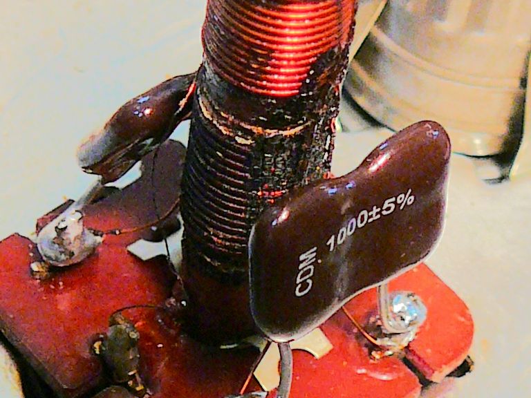 The resistance on the primary should measure 6.8 ohms according to the Sams schematic. I measured it at 6.8 ohms. When the caps were off, I measured the other coils; both of them have continuity and they measure at .2 ohms. I just noticed that the Sams parts list has a note stating, "R-Y windings = .2 ohms." I tried the TV again after those cap replacements and saw no change. I'm not sure how much faith to put in those resistance measurements. I'd feel a lot better if these coils looked brand spanking new. Phil Nelson Last edited by Phil Nelson; 04-18-2015 at 09:10 PM.
|
| Audiokarma |
 |
|
|


 Linear Mode

