
|
|
|
#16
 09-03-2017, 12:52 PM
|
||||
|
||||
|
It's not ansynchroguide, I said that in the beginning. I found somewhere that the 630 had a synchro-lock circuit, must be what the synchroguide evolved from.
In any event, I'm going to do what wayne suggests and look at the discriminator. There's got to be a reason why it's acting up, just need to figure it out.
__________________
Evolution... 

|
|
#17
09-03-2017, 12:54 PM
|
||||
|
||||
|
The Redbook (page 265 on the link above) has an extensive procedure for aligning the horizontal. jpg of synchroguide with waveform info attached. "Phasing" is the sinewave coil, the "test points" are there to make it easier to jumper it.
Ok, re-read the original, you were aware it is not synchroguide... And had followed the alignment instructions.. the Redbook also mentions checking R200 and R202 for this problem.. Last edited by teevee; 09-03-2017 at 01:01 PM.
|
|
#18
09-03-2017, 05:50 PM
|
||||
|
||||
|
Im very familiar with synchroguide, if that's what this was I wouldn't even be here. What's throwing me off was that reactance tube, but I guess it's not a whole lot different from the later stuff when you think about it. Just a different way of accomplishing the same thing, and the waves look a little different.
Here's what I've been able to find out, so far there are nice sine waves arriving at the 6AL5 and everything looks normal- that is still I put the plate cap back on the HO tube! Here's h-drive and h-sine with the plate cap removed and no signal input to the chassis, everything looks normal: And now with the plate cap on: See that little hump? Apparently the flyback is causing it to show up, so effectively it's self triggering because that pulse has more amplitude than a regular sync pulse does- so any sync pulses from a normal video signal applied to the chassis simple gets drowned out. I'm still waiting for the flyback tuning capacitor to show up from mouser, so I won't know if the lack of it is what's causing this till it arrives. I really hope that's it, because I'm out of ideas here.
__________________
Evolution...
|
|
#19
09-03-2017, 07:05 PM
|
|||
|
|||
|
Guys, I'm a little confused here. Nick, you say the original tube is a 23CP4 and you are now using a 10SP4 with the same chassis. The 23CP4 is a 110 deg tube with a 1.125" diameter neck. The 10SP4 is a 50 deg tube with a 1 7/16" dia neck. I don't see how you could get a yoke that was intended for a 23CP4 to accommodate a 10SP4. The yoke for a 23CP4 is just too small in diameter to fit on to the neck of a 10SP4.
Am I missing something here? Also, the sockets are very different between these two CRTs. Last edited by Tom9589; 09-03-2017 at 07:37 PM.
|
|
#20
09-03-2017, 08:01 PM
|
||||
|
||||
|
I honestly don't remember what it was, could have been a 24CP4 for all I know I gave it away. The yoke is the correct size for a 10" CRT, but I'm going to have to play with the width coil to get the right raster size.
__________________
Evolution...
|
| Audiokarma |
|
#21
09-03-2017, 10:39 PM
|
||||
|
||||
|
Quote:
I don't see any explicit connection from the flyback. (correct me if I missed one on the schematic). Assuming no intentional connection: Where exactly is that sine wave and spurious pulse? On one of the 6AL5 plates, right? (pin 2 or 7). Both good and bad waveforms are with nothing attached to antenna input, right? If so, you should try again with a good signal input. See if you get the sync pulse superposed on the sine wave properly then, and check both plates to see if you have same polarity sync and opposite sine wave. Look for the spurious pulse IN ADDITION TO the sync when connecting/disconnecting the HO. Maybe the HO is oscillating back into the tuner. If so, you need to see if the spurious pulse is still there when you have a good signal. If it's still there, that's what you need to chase. But if a normal signal swamps out the spurious pulse, then the bad phasing is still caused by something else.
|
|
#22
09-04-2017, 08:01 AM
|
||||
|
||||
|
Wayne,
Yes, the odd pulse appears at the 6AL5, and it's there whenever the flyback is in operation with signal at the antenna or not. What happens with a signal present is that odd signal is triggering the oscillator and the normal sync pulse that should be locking to horizontal just gets taken along for the ride so to speak. It looks like this one with signal applied: I don't see how that pulse could get coupled into the phase detector either, since there's no connection present. But that 6AL5 is positioned right below the flyback, so I suppose it's possible the pulse has such a high amplitude its radiating into the circuit and the 6AL5 is the antenna. There's no shield around it surprisingly enough, but I could try adding one to see if it helps matters. *just noticed the normal sync pulse does indeed have a higher amplitude than the spurious one does, but once horizontal is locked to the spurious pulse there's apparently nothing I can do to get the circuit to 'choose' the correct sync pulse and lock to that. I have to get the spurious pulse out before this thing is going to work properly.*
__________________
Evolution...
|
|
#23
09-04-2017, 09:08 AM
|
|||
|
|||
|
24CP4 makes sense. It has the same diameter neck and the difference between the deflection angles isn't so great (90 deg vs. 50 deg)
The reason I question the 23CP4 is that was the first CRT I ever replaced in my parents' TV. You don't forget your first.
|
|
#24
09-04-2017, 03:46 PM
|
||||
|
||||
|
Is the flyback in the open, or in a cage?
EDIT: The red book drawing looks like all the H section tubes and the flyback are in a common enclosure. Does the 6AL5 socket have grounding fingers for a shield? Last edited by old_tv_nut; 09-04-2017 at 03:53 PM.
|
|
#25
09-04-2017, 04:29 PM
|
||||
|
||||
|
Nope it doesn't, and honestly I can't see how it ever worked properly without a shield it's just too noisy. I took a 7-pin extension cable and put the 6AL5 far away from the flyback, now it's pretty stable though the h-hold control has a hair trigger. Been watching the Matrix for a half hour now, it hasn't skipped a beat.
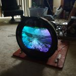
Linearity is really good too. Guess I'll just have to remote mount the 6AL5, I'm satisfied that it will be stable enough come color wheel time. Speaking of which, I'm off to begin building the motor control chassis!
__________________
Evolution...
|
| Audiokarma |
|
#26
09-04-2017, 05:11 PM
|
||||
|
||||
|
I can't quite stop wondering what's wrong. Does pin 6 of the 6AL5 have a solid ground?
also, is pin 5 a clean, solid -2 volts? The red book shows it connected to a -2 volt supply, I didn't see where it went on the SAMS. {corrected to say it goes somewhere on both versions} Last edited by old_tv_nut; 09-04-2017 at 05:33 PM.
|
|
#27
09-04-2017, 07:10 PM
|
||||
|
||||
|
Everything about the 6AL5 is as it should be, it's just too close to the flyback. Remember that this is not a stock 630, the fly makes more HV and has higher pulses being driven into it (chassis now uses a 6CD6 instead of a 6BG6). I held my scope probe in the same location as the 6AL5, there's a ton of horizontal noise in that area so it's unavoidable that some of it would be coupled into the tube. Even when it's remote mounted it's not perfect, my extension harness isn't shielded so it can be better than it is now.
__________________
Evolution...
|
|
#28
09-04-2017, 07:33 PM
|
||||
|
||||
|
You may be able to get away with keeping the tube in it's socket, and surrounding the topside of the tube with a shield...
__________________
Tom C. Zenith: The quality stays in EVEN after the name falls off! What I want. --> http://www.videokarma.org/showpost.p...62&postcount=4
|
|
#29
09-04-2017, 07:51 PM
|
||||
|
||||
|
That was the first thing I tried, I'm telling you that tube is so close to the flyback that the only solution is to move it out of the cage. The terminal directly above it carries a 3kv horizontal pulse, so that's probably the one cause the trouble.
__________________
Evolution...
|
|
#30
09-04-2017, 08:25 PM
|
||||
|
||||
|
Quote:
 I wonder if this is the reason some sets had a 6AL5 mounted under the chassis on it's own little metal bracket , it was picking up some unwanted signal or other ... I wonder if this is the reason some sets had a 6AL5 mounted under the chassis on it's own little metal bracket , it was picking up some unwanted signal or other ...
|
| Audiokarma |
 |
|
|


 Linear Mode

