
|
|
|
#46
 06-01-2011, 09:31 AM
|
||||
|
||||
|
Quote:
What you need for the grinding on the crt button is diamond impregnated burrs to put in your Dremel. The diamond burrs will grind glass very easily. I purchased an entire kit assortment on ebay and they were not at all expensive. Standard carbide burrs will NOT do the job. Don't even attempt with anything less than diamond. After you expose some of the wire it will be difficult to get solder to stick. I took a small patch, of Chemtronics solder wick and placed it over the wire stub and saturated the patch with solder. Then I tack soldered a fine wire lead to the solder patch that was stuck to the wire stub. You only need to expose the tip of the wire, perhaps .010" I would not risk going much farther. You will not be able to attach a wire directly to the stub because the glass will sink the heat from the wire and you cant risk heating the glass much because you could crack the glass if it gets too hot. John Folsom has also accomplished wire attachment using a silver epoxy compound. Because you are attaching to a grid wire, there is very little current flow and the silver epoxy is conductive enough to work in this situation. Being as your issue is a grid wire, this epoxy method may be your best bet. Good Luck!
__________________
Vacuum tubes are used in Wisconsin to help heat your house. New Web Site under developement ME http://AntiqueTvGuy.com 
|
|
#47
06-01-2011, 10:46 AM
|
||||
|
||||
|
The silver filled epoxy worked well on the K, G1, G2 and convergence leads on a 15GP22. I obtained this tube with a smashed base and the 4 wires broken off flush with the glass. I put a little collar around each broken wire, and filled the collar with epoxy and inserted a length of very fine flexible wire into the top of the collar and let it cure in place.
Then all the CRT leads had long pigtails attached and threaded into the base pins and the base slid back into place, soldered, and the excess pigtails cut off. The 15GP22 tested good after the operation was complete.  Sadly, several years later, when it came time to use the repaired 15GP22 in a set, it had the dreaded purple glow.  I speculate that the CRT was damaged when the base was broken, but it could also have been a spontaneous leak at the glass-to-metal joins at the ultor, or the ultor seam weld. If our first shipment of 15Gs to RACS is successful, this tube will be cut open and leak checked. The only down side to the silver filled epoxy approach is that the epoxy is quite expensive, and might not be justified for a "common" tube like a 10BP4. Sorry, did not intend to hijack the thread....
__________________
John Folsom
|
|
#48
06-01-2011, 11:41 AM
|
||||
|
||||
|
Thanks, that gives me some good ideas. The silver epoxy sounds easier and safer than grinding. While the 10BP4 is a common tube, it would still cost something to replace, so anything less than replacement cost is a bargain.
I wouldn't be so gung-ho if it had tested weak, but the tester needle jumped right up into the Good zone, no wake-up period required. So close . . . just one little wire! Phil Nelson
|
|
#49
06-01-2011, 05:29 PM
|
||||
|
||||
|
This gives me some good ideas for a spare 17" tube I have that has a busted lead.
Tom C.
|
|
#50
06-01-2011, 06:45 PM
|
||||
|
||||
|
I did the spring thing on a hard to find tube once.
It was the HV anode, it goes in the base on a 9QP4 (used in the little GE portables from the 50's) I smoothed it out flat, put some Dag on the area where teh wire went into the glass and rigged up a flat plunger and spring that pressed against it. I siliconed the base on tight then released the wire, soldered it in place and it worked fine. There's very little current on the HV anode and probably even less on the G1 G2 leads so this might work as well. Another tube I repaired was the 20" tube in a Wilcox Gay TV, tube was rebuilt and in great shape but with one wire broken off where the cap had been knocked off. On that one I took a sharp pick and dug around the wire stub until I had enough to solder to (no power tools). I cleaned it with Rustoleum and tinned it with Plumbers Flux and 60/40 solder. I couldn't get a really strong connection but it was good enough to work. The heat from a 25 watt soldering iron doesn't seem to be enough to hurt the glass, at least i didn't in this case and I applied it for quite a long time to get it hot enough to stick. I used very fine wire so pulling and tugging on it wouldn't knock it loose where it was soldered.
|
| Audiokarma |
|
#51
06-01-2011, 07:16 PM
|
||||
|
||||
|
I suspect with heat you can do it safely, much like with cataract removal- just take it slow and give the glass a chance to heat up and establish a thermal gradient (i.e. hold the iron close to the glass for a bit, 15 minutes or so, before actually touching anything). So long as you don't have a sharp temperature gradient from an instant addition of heat or cold, it should be OK.
|
|
#52
06-01-2011, 08:13 PM
|
|||
|
|||
|
Wow, Eric's dab-of-dag idea with a springloaded pressure pad sounds great. It wouldn't need precision 'targeting' like the needle/cat's-whisker. oc
|
|
#53
06-02-2011, 05:59 PM
|
||||
|
||||
|
The cut-away cap idea sound like a winner. you can align the new wire right into the little indentation where the broken off wire is. Put one drop of liquid silver solder there and then heat up the male pin on the cap, let the heat travel through the new wire to the joint with the tube, put a drop of solder on the male pin and watch the whole thing come together.. That silver solder makes a really strong bond.
http://www.amazon.com/gp/product/B00...G964GE853TH8GB Keep the temperature to a minimum as I believe that high solder temps break down the bond between the glass and the wire as it goes into the tube, as the metal heats it expands and as it cools it contracts. There's your leak.. at least that's what happened to me. Grinding the glass would be the last choice for me. silver solder is considered a hard solder melting temp is around 840F. Soft solder is below that temp. The seller says that his paste melts at 430F.. Last edited by charokeeroad; 06-03-2011 at 09:07 AM.
|
|
#54
06-08-2011, 10:17 PM
|
||||
|
||||
|
This TV has a non-polarized electrolytic across the vertical centering control:
 The parts list describes the cap as "1 ohm Z @ 60 cycles, 3 volts N.P." The original cap has been replaced with a polarized electrolytic: 1000 MFD / 6 VDC. Is that an appropriate replacement? If not, what's better? The full schematic is here, in case you're curious: http://antiqueradio.org/art/Capehart661-PSchematic.jpg Thanks! Phil Nelson
|
|
#55
06-08-2011, 10:41 PM
|
||||
|
||||
|
I encountered one during my Motorola 19K1 restoration. I used a capacitor impedance calculator and came up with 2,650 uF.
I used a 2,200 uF @ 25v cap from Mouser like this. It worked just fine.
|
| Audiokarma |
|
#56
06-08-2011, 11:06 PM
|
||||
|
||||
|
A capacitor impedance calculator -- good thing to bookmark.
Thanks for the info. Phil Nelson
|
|
#57
06-09-2011, 07:22 AM
|
||||
|
||||
|
Quote:
John
|
|
#58
06-09-2011, 10:44 AM
|
||||
|
||||
|
Quote:
If you need to replace it, it should be a non-polarized cap, usually 1000 to 1500uf. Unless the cap is shorted or completely open, I wouldn't bother replacing it. It is shunted by 30 ohms. Chuck
__________________
www.myvintagetv.com Learn from the mistakes of others - You can't live long enough to make them all yourself.
|
|
#59
06-15-2011, 11:31 PM
|
||||
|
||||
|
Fixing the CRT lead was simpler than I expected. I was able to attach a stranded lead to the stub with silver solder, but I knew from before that the joint would be very fragile. I applied silver-filled epoxy all around the joint and let it cure. The tester shows strong emission. After I reattach the cap, I'll have a nice 10BP4.
I found a few different sources for silver-filled epoxy. This came from Mouser, $31 for 14 grams (about 1/3 oz.). The repair required only a miniscule amount. Thanks again for all the advice. Phil Nelson Phil's Old Radios http://antiqueradio.org/index.html  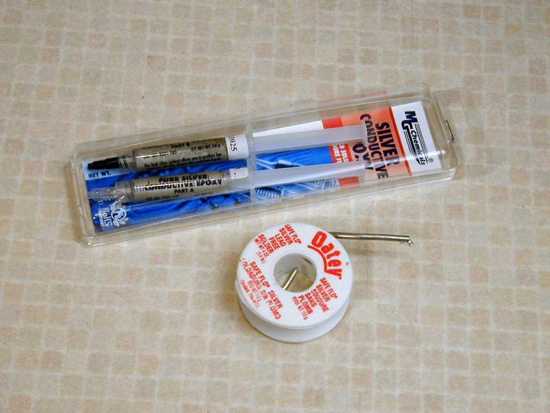 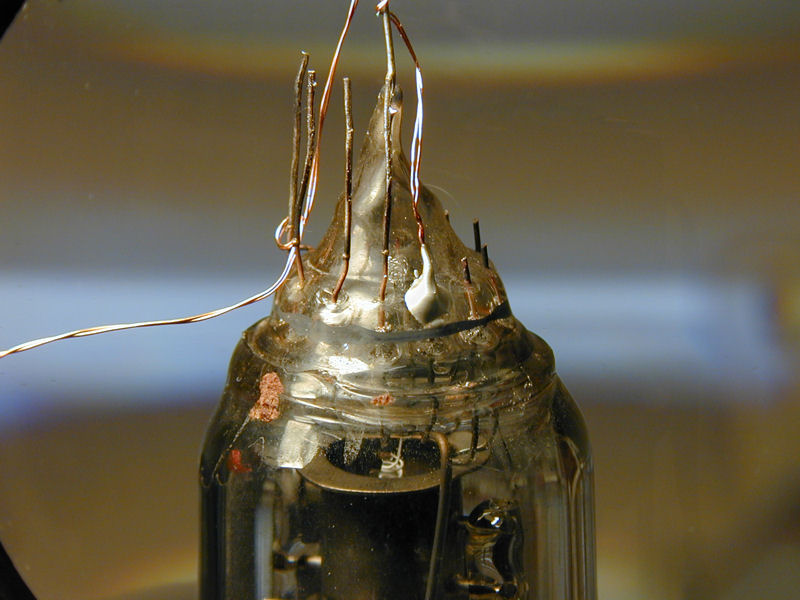 
|
 |
| Thread Tools | |
| Display Modes | |
|
|


 Linear Mode

