
|
|
|
#46
 04-29-2009, 07:54 PM
|
||||
|
||||
|
While doing some fine tuning of the set I realized that the Zenith Wavemagnet I picked up has the right inductance to use as a loop for the AM section of this set. I tried it without doing any alignment and the reception was amazing.
This might be pretty good for AM DXing. John 
|
|
#47
04-29-2009, 08:38 PM
|
||||
|
||||
|
I need some advice on dealing with a problem with the volume control on this set. It's a 1 meg composition pot tapped at 500K and 250K. It has a hollow shaft. The Photofact doesn't list any replacements other than Sylvania so it's pretty much going to be impossible to find.
The resistance from one end to the other is 1.2 Meg, which isn't so bad. The Symptom is that the volume jumps up to a loud leve when I start turning it up. I've attached a scan of this section. It seems that a spot was burned in the conductive film near the bottom of the pot. Possibly when paper cap C25 was leaky. As you go past this spot the resistance measured at the wiper jumps from 25 ohms to 250 ohms. If I measure the resistance to ground from the other taps they jump down to the correct value when the wiper is in the center of this spot. I imagine the conductive trace having a burned spot in the center of the trace, but good on both sides. I've attached a sketch of what I think it might look like. I think the taps are there to keep the tone the same as the volume is changed. I could just short the 250K tap to ground. I'd lose a portion of the range. The tone might sound a little different. This would be the easiest solution. I could try coating the spot with aquadag to cover the burned spot. If it's small enough, it might not be noticiable. To get at it I have to remove the CRT, the front panel, and the plate that holds the pulley for the dial cord. I hope to avoid that. Any other suggestions on how to attack this problem? John Last edited by jeyurkon; 11-14-2009 at 07:11 PM.
|
|
#48
04-30-2009, 03:45 PM
|
||||
|
||||
|
Well, the problem with the volume control wasn't what I thought it was, and the problem was fixed by an unfortunate accident.
Instead of a burned spot on the resistive trace, it was where the terminal on the ground side was riveted to the phenolic board with the resistive trace. I didn't notice that a tubular capacitor that is on the end of a coax running to the wiper of the volume control was too close to a resistor. It arced through the paint on the capacitor while I was watching and made violent discharges in the volume control.  I expected the worst. I expected the worst.  But, it turns out it just improved the connection so now the volume control tests and works perfectly! But, it turns out it just improved the connection so now the volume control tests and works perfectly!  John
|
|
#49
05-17-2009, 01:12 AM
|
||||
|
||||
|
While I was able to adjust the set to give a good picture, there was still a problem with the horizontal. I wasn't able to adjust it according to the service literature. Basically you're supposed to remove the discriminator tube, the 6AL5, adjust the frequency until the bar moves slowly across the screen and reinsert the tube. It should lock in at this point and then you adjust the phase.
They then have test the pull-in range by adjusting the frequency CCW until it unlocks, then adjust it back slowly until it locks in and you count the number of bars just before it locks in. Then CW and count the bars. They're supposed to be between 3-4 bars in both cases. In my case when I turned it one way it would just slowly drift across. In the other direction it wouldn't unlock until I made many turns. I also wasn't able to adjust the phase independently. I checked all the caps and resistors. I replaced the micas. Nothing helped. I started to suspect the horizontal oscillator transformer. But, I noticed that the DC level on the grid of the 6AU6 control tube was -1V when it should have been -3V. The 6AU6 is used as a reactance tube to control the frequency based on the output of the phase discriminator. -1V put it at one end of it's control range so it could only adjust the frequency in one direction if the free running frequency was set correctly. The bias is determined by dividing down the -125V supply. First they divide it down to -30V with a low impedance divider then down to -3 with a 10meg and 1meg in series. I checked those and they were o.k. I was getting close to modifying it to give the right bias when I decided to swap the 6AU6 even though it tested as new and seemed to work. Well the bias went to -3V with the new tube and I was able to align the horizontal sweep as per the service manual. The grid on the 6AU6 was drawing 0.2 microamps at -1volt. My tube tester isn't going to notice that. Now the only problem I have is with the FM. Although it worked great in the beginning, it is now fading out after 4 minutes. It runs for 4 minutes after turning on and then suddenly the volume drops. I've replaced two micamold caps. One was leaky, the other was o.k. Some resistors are out of spec, but I don't think they're at fault. What is curious is that the AM function works fine even when the FM has dropped in volume. They both use the same circuitry except different IF transformers and osc frequency. There must be a clue in this. You can see the schematic for the radio section on the last page of: https://www.msu.edu/~yurkon/Sylvania_9-2_Sup1.pdf This is getting to be really frustrating. I swapped all the tubes in the radio after my experience with the horizontal 6AU6 but it didn't make a difference. Any suggestions for what to look for would be welcome. I'd like to get it off my bench so I can work on my alignment generator and get it working. I want to touch up the alignment since I had to rewind one of the video IF transformers. I'm also working on making a bezel for the 12" version of this set. A friend drew a mold up for me based on my measurements. I didn't notice however that the had made the face a cylinder instead of a sphere. It wasn't obvious in the preview. It became obvious when the shop I'm using tested their programming on a shape board. If I'm able to cast a 12" bezel then I'll put a 12LP4 into the chassis. It should really be a 12VP4 but I'm unlikely to find one of those. I'll have to add a screen bias supply. One of the 16" Sylvania shows a circuit to do that, based on this power supply. This is basically changing it from a 1-076 model to a 1-128 model. I have the cabinet from my family's 1-128, just nothing is left of the electronics. The 1-108 chassis was used in both. If I can't successfully cast a bezel I'll refinish the 1-076 cabinet and stick with it. John
|
|
#50
05-17-2009, 06:58 AM
|
||||
|
||||
|
Have you re-capped the entire set?
Bill Cahill
__________________
"Tubes are those little glass things that light up orange unless there is a short.. Then they light up all pretty colors..." Please join my forum. http://www.tuberadioforum.com/
|
| Audiokarma |
|
#51
05-17-2009, 11:41 AM
|
||||
|
||||
|
Quote:
The radio section is comletely independant except for the 6AU6 1st AF and 6Y6 power amp which is shared by the TV. The problem only occurs with the FM. The TV and AM audio are fine. There was only one electrolytic in the radio section and I changed that in the beginning since it was shorted. I changed the two micamolds that were in the radio. There are other micas that aren't micamolds. I'm hoping it's not one of these micas because I'd have to remove most of the other components just to get at them. Also, I've checked the HV to the radio and it doesn't change. There should be 215V on the plates but it's 238V. I've tried lowering it by running the set on a lower voltage with a variac, but this doesn't change the fading. John
|
|
#52
05-18-2009, 09:52 PM
|
||||
|
||||
|
Found the FM fading problem. Had to resort to using component cooler. It's the 2nd 10.7MHZ IF. It looks exactly like the Ktrans that Robert Casey repaired. I suspect it's the same problem.
Anyone have a 122-0011 Sylvania IF or Merit FM-254 you're willing to part with? John
|
|
#53
05-22-2009, 10:37 PM
|
||||
|
||||
|
I found an FM-254 and ordered it, but decided to repair the original IF instead. The FM-254 would have been too difficult to use because of the pin-out.
In the first photo you can see the problem with the mica capacitor. Although it looks like silver migration might have been the problem, it was actually a break in the silver on the bottom half that you see. It appears that the mica was bent when installed. It was actually tuned to work with it open. Then it would eventually make contact as it warmed up and detune. I measured the capacitance on the good side at 23pF. Just for the fun of it I measured the thickness of the mica which was 0.045mm, the area that forms the capacitor as 3.5mm x 5.5 mm and calculated the capacitance assuming a relative dielectric constant of 6 for mica. I came up with 22.7pF. I installed two 22pF silver mica capacitors internally. You can see the result in the right hand photo. I think most people install them outside during the repair, but there was room and I was confident of the value that I needed. The FM works great again and is now stable. It only took a minor touch-up on the alignment on the side that was good, on the other side I had to back the slug out many turns. I think the IF had been this way since it was made. I'm glad that this set didn't have any serious problems to solve since it was my first restoration. Even the minor problems I had to deal with might have stumped me if not for the wealth of information that many of you have made available on your web sites. John Last edited by jeyurkon; 11-14-2009 at 08:02 PM.
|
|
#54
05-23-2009, 05:41 AM
|
||||
|
||||
|
John , you have done a great job .
Such a neat set to restore . If you ever need a volume control , I "might" have one . I've got a big box of different ones that were salvaged by a TV / radio guy back in the day.....
|
|
#55
05-24-2009, 01:53 AM
|
||||
|
||||
|
Quote:
John
|
| Audiokarma |
|
#56
05-30-2009, 09:27 PM
|
||||
|
||||
|
Analog Reception
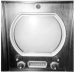
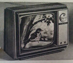
Since I won't have the set back in a cabinet by the time analog TV is history, I thought I should shoot a couple of photos of over the air broadcasts.
The on the left is Channel 12 in Flint Michigan, 36.1 miles away. The one on the right is Channel 6 in Lansing about 7.4 miles away. For channel 6 I don't even need a rabbit ear. Just 2" of wire. The key-stoning you see in the right hand photo is because I'm close to the TV and at a slight angle. I think the slight fuzziness is because I need to align the video IF. I have to finish restoring my Hickok alignment generator first. I've also been slow in starting on the cabinet because I've been tracking down all the minor problems I could find. One was a crackling in the sound as the set warmed up. I thought I'd find that one of the electrolytics that I decided to keep was failing and I'd have to swallow my pride. It turned out to be the 6Y6G audio output tube. I swapped it and the crackling went away. Swallowing my pride will come later. I wonder if there is a heater to cathode short developing with it. The tube is coated so I don't think it was secondary emission from the glass. John Last edited by jeyurkon; 11-14-2009 at 08:03 PM.
|
|
#59
09-09-2009, 10:32 PM
|
||||
|
||||
|
Quote:
|
|
#60
09-10-2009, 09:59 PM
|
||||
|
||||
|
Mold Photos
Here are the photos again of the bezel/mask mold that I'm making. The left photo is the 10" bezel, the center is the 12" rear half of the mold after machining and the right is after my attempt at polishing.
John
|
| Audiokarma |
 |
|
|


 Linear Mode

