
|
|
|
#46
 11-02-2012, 11:03 PM
|
||||
|
||||
|
Quote:
I recall trying to find a vertical sync. problem on my RCA 9TC275 for quite a while and I eventually traced it to a mica look-alike paper capacitor. 
|
|
#47
11-04-2012, 06:49 PM
|
||||
|
||||
|
After recapping the chassis and after the preliminary checks, I applied power for my first time. The chassis is on the bench with deflection yoke, convergence coils and tuner attached but without the CRT.
The set powered up and appeared healthy. The first check is horizontal output performance: I checked the horizontal drive: RCA notes says 180p-p waveform and I measure 150v p-p. I adjusted the horizontal efficiency coild for minimum HO Tube cathode current. The HO Tube initially very slightly started to glow red on the plate after about 5 minutes and after adjusting the efficiency coil for minimum cathode current, the red glow disappeared. Similar to the other CTC-5 thread, the HO Tube bias is a bit low and I attributed this on my set to the low drive at 150v p-p. I tried swapping the 6CG7 Horizontal Oscillator Tube with the 6CG7 Vertical Oscillator. The other tube reduced the drive to 130v p-p which seems to me that I have a couple of tired old tubes. (All the tubes are original to the set!) This was one of the best preserved old sets I have ever had a chance to work on (in recent times). I plan to check the full alignment as I will be curious if, under this set's almost ideal 55 year life, how much it will have drifted.
|
|
#48
11-12-2012, 09:27 PM
|
||||
|
||||
|
I made/ obtained some extension cables to run the chassis with the CRT. I powered up the set with the CRT and the sweep circuits appear okay apart from minor vertical non-linearity. All the paper caps on the vertical sweep board have been replaced and since the height control is at it's limit, I suspect the 2.2Mohm oscillator plate resistor has drifted. I will investigate later.
The brightness control functions correctly at turn on but in about five minutes, the brightnes increases. I found the negative voltage for the brightness control drifting upward (towards positive). The negative voltage is obtained from the horizontal output tube grid leak bias and the 470kohm resistor coupling to the brightness control bad. So far so good. I have been tracking down an intermittent corona from the HV cage. I used a long piece of plastic heat shrink tubing as a listening tube and tracked down the corona to the focus pot. I shall take this apart and investigate. I suspect the focus pot is troublesome in these sets.  I fed an RF modulated rainbow pattern to the antenna and see video of sorts on the CRT. Contrast is low and picture is washed out: I shall go through the video chain later. Following the discussion on CTC5 low HV, I measured this set's HV at about 23kv. (I measured the HV with the Heathkit VTVM and HV probe I bought new in 1971!) I am pretty sure the calibration is still reasonable as I have recently compared other sets HV measurements. The measurement tolerance I would put at no more than +/-1000v. In any case, the raster on this set is brighter than I would have expected for a 21AXP22A. It is bright enough to watch in a typical evening lamp lit living room although it may be tough to watch in a sunlit room if the curtains aren't drawn.
|
|
#49
11-12-2012, 09:34 PM
|
||||
|
||||
|
23KV is a little high, Should be 20KV per the RCA manual, That set will not be very bright compared to the newer sets.
__________________
"It's a mad mad mad mad world" !! http://www.youtube.com/user/mwstaton64?feature=mhee
|
|
#51
11-13-2012, 07:06 AM
|
||||
|
||||
|
Quote:
|
|
#52
11-13-2012, 07:43 AM
|
|||
|
|||
|
I did the same (cleaned up the work that had been done). I did notice the small cap (22pf IIRC) off the plate mounted on the bottom had NOT been removed and the other small cap a 330pf had not been changed to the 390pf (again IIRC). I don't know how much effect these changes would have had, but will do them next time I pull the chassis.
|
|
#53
11-13-2012, 09:07 PM
|
||||
|
||||
|
If you put it back to original, you wont like it. You will have HV loss and a blurred dim picture if the contrast is turned up all the way. I thought there was something seriously wrong with mine until I found an article on it. There is a thread or 2 on that subject here on VK
__________________
"It's a mad mad mad mad world" !! http://www.youtube.com/user/mwstaton64?feature=mhee
|
|
#54
11-13-2012, 10:05 PM
|
||||
|
||||
|
Quote:
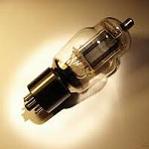
I removed and disassembled the focus pot for examination tonight. As I suspected, it had an open carbon track with a big burn hole. (See picture). The pot was replaced previously as there remained a trace of the old pot center lug attached to the soldered wire. Last edited by Penthode; 11-13-2012 at 10:09 PM.
|
|
#55
11-26-2012, 07:12 PM
|
||||
|
||||
|
Success on the weekend! I have a reasonably good picture on my CTC-5 and it is running well. I have roughly set up purity and static convergence: I haven't touched the dynamic convergence just yet. Pictures to follow.
The third video IF was intermittent and I ended removing the tube socket because of the pin connections. I slightly bent the socket pins and re-installed the socket with virtually no damage to the copper trace: a good solder sucker is indespensible. The alignment of the third stage was affected. I plan to go through and test the complete RF/IF alignment shortly. In the meantime I simply touched up the last IF coil. The 12BY7 developed control grid current after running a few minutes. That was the only bad tube in the set. (All the tubes looked original although the 12BY7 video amplifer had possibly been changed before: the rest of the RCA tubes read made in USA and the RCA 12BY7 read made in Canada. I was beginning to investigate the alignment a couple of weeks ago when the RF Output lead of my HP8601A slipped off and hit the 5U4 rectifier socket while the set was on. Needless to say, it blew up the output hybrid amplifier of the generator. Fortunately, I recalled an article in which Matthew D'Asaro reverse engineered the HP hybrid and is offering them for sale. I purchased one and once it arrives I trust I will have my alignment equipment back in the running. Lastly, after examining the video off the CRT with the contrast control modification, I am beginning to have second thoughts about keeping it. I notice with the contrast control advanced, the black level varies with picture CONTENT. At low contrast, it doesn't appear that bad. I believe it may be due to the bypass capacitance loses the DC level. I will look at this more and may consider modifying the contrast circuit back to original. It is interesting that the interaction of brightness and contrast control adjustment is removed with the modification at the expense of superior DC coupling. I'd be curious to hear from others with similar thoughts or alternative arguements. Last edited by Penthode; 11-28-2012 at 12:50 PM. Reason: Wrong word! "content" instead of "control"
|
| Audiokarma |
|
#56
11-27-2012, 10:01 PM
|
||||
|
||||
|
I worked on the CTC5 again tonight. For the last day since I got the set working, I have been scratching my head over a dynamic convergence problem. The convergence was really bad and the convergence control worked but would not bring the image into convergence.
I could not find anything electrically wrong. I ended up removing the convergence plug and found the convergence considerably better! In fact all the image seemed to require was static convergence. Puzzling over this the only thing I could remember is when disassembling the convergence assembly for cleaning, I may have reassembled it incorrectly. I then reversed the removable horseshoe windings and the dynamic convergence adjusted fine. In fact I am surprised how well it converged, especially after stories I have heard about the difficult adjustment procedure. The only problem I found was having to touch up static convergence frequently as I proceeded through the dynamic adjustments. I am very grateful the 21AXP22A appears healthy and the greyscale adjustments were no problem. I have a temporary focus pot in place and a 2watt Allen-Bradley pot is on order. Other than replacing most of the paper capacitors and a few resistors and one tube, the set appears in good running order. I shall bench test it for a few weeks to keep an eye on the electrolytics to see if they continue to hold up. The last thing will be to go over the IF alignement when I get my sweep generator fixed. I have taken some low res photos with my camera phone. I suppose some pictures are better than none. In one photo you will see how I was able to power it up attached to the CRT. I made extender cables for the HV, tuner to IF coax and the deflection yoke. I could not find a suitable donor Admiral set for the convergence socket and so positioned the chassis on a sturdy surface adjacent to the CRT so no extender was required. Similarly the CRT socket was easily attached from the same position. Note the subchassis B+ transformer. The main chassis transformer is for filaments only. This was for the Toronto 25Hz market in 1956. Note also the photo of the picture off the screen was via a mirror: my current repair shop is limited in space and the front is up against the wall, hence the mirror. Last edited by Penthode; 11-27-2012 at 10:06 PM.
|
|
#57
12-04-2012, 11:30 AM
|
||||
|
||||
|
I did some more work on the set this past weekend. Thanks to Matthew D'Asaro, I managed to get my HP8601a sweep generator running again. I have had the HP8601a for years and it is a great machine. You may recall the RF Output lead slipped off and hit the 5U4 rectifier while on, when I was in the process of beginning IF alignment. This blew up the Hybrid output amplifier and thanks to Matthew's reverse engineering skill, he duplicated the HP Hybrid amplifier!
The audio IF alignment was slightly off and it has been fixed. The 4.5MHz trap (on the chrominance chassis) was way off: this would have accounted for the bad 920kHz beat. I initially just swept the video IF amplifier to study the response. The response was extended incorrectly to the sound region. I later found the overcoupled transformer between the first and second IF stages was misaligned. The traps and rest of the stages were touched up and it looks fine. I have not examined the tuner nor the chroma chassis alignment just yet. I decided to "bake" the chassis in the cabinet. This gave me the opportunity to set up the purity and convergence properly for the first time. I had no problem with purity and given time, the convergence ended up pretty good. It was reassuring to find all the convergence controls worked. In the CTC5, I especially like the location of the controls on the front which made it very convenient to simply sit in front of the screen as you make the adjustments. Despite the 21AXP22 testing excellent, the picture is still pretty dim by modern standards. But I can get an acceptible picture without blooming so long as the room lighting is subdued. Bothered by the rather poor DC clamping in the video, I tried reverting the contrast control to original: I will open this in a separate thread. Last edited by Penthode; 12-04-2012 at 02:31 PM. Reason: spelling error
|
|
#58
01-22-2013, 07:32 PM
|
||||
|
||||
|
I have been working intermittently on my Whitby set. I have checked the alignment of the Front End, realigned the Video IF and Sound IF apart from the earlier replacement of capacitors, resistors etc. I still haven't gotten around to the chroma bandpass, chroma demodulator and matrix alignment.
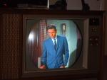
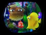
I last weekend fixed (at least tempoarily) the red static convergence pot, replaced a few tubes and increased the horizontal drive marginally. With the drive increase and the efficiency coil adjustment, I have the horizontal output current at about 200mA. You may recall I opted to not change the electrolytics. They were all healthy and the two Canadian Mallorys used in the 25 Hz power modification are not too bad. The leakage on the Mallorys remains at about 200uA. I have been running the set a few hours at a time the last few weeks and the only problem has been vacuum failures. When I received the set, all the receiving tubes, including the picture tube, was original. I have now had 4 tubes fail and be replaced (3rd VIF, Video Output, 3.58 MHz oscillator and the Z demodulator. I have since replaced the X demodulator, 1st video amplifier, the Horiz. Damper, Focus Rectifier, HV Rectifier and Horiz Output Tube. With the extra drive, the blooming effect has reduced and focus has improved. The picture is improving and with a little more work it should be quite acceptible. I have attached some photos of it working this evening. Note the dolly which helps me rotate the heavy cabinet. I have made up a bunch of extender cable so that I can readily pull the chassis and hook it up to the CRT for further technical investigations.
|
|
#59
01-22-2013, 08:04 PM
|
||||
|
||||
|
Wow, thats a beautiful picture.The convergence looks really good!
|
|
#60
01-22-2013, 09:35 PM
|
||||
|
||||
|
Quote:
The chroma demodulator alignment is still required. But I am pleased with the incremental improvements in the picture quality gained over the past few weeks.
|
| Audiokarma |
 |
|
|


 Linear Mode

