
|
|
|
#47
 01-02-2009, 08:33 PM
|
||||
|
||||
|
I have the RCA Field service guide for your set - I'll look at it tomorrow and see what I can find on the lampholder and the two lamps.
Cheers,
__________________
Brian USN RET (Avionics / Cal) CET- Consumer Repair and Avionics ('88) "Capacitor Cosmetologist since '79" When fuses go to work, they quit! 
|
|
#49
01-03-2009, 01:41 AM
|
||||
|
||||
|
I did the convergence tonight.
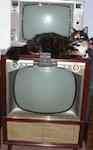
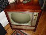
I did pull the cone back on that speaker to try to get in there and solder on a new wire, but there was only maybe a 1/16 in. of wire left to solder onto inside that speaker, and there was no way to solder a new wire to it without touching a paper portion of the speaker with the iron. I did fix it at first, but I didn't solder it well enough for the wires to stay attached, when I tried a second time I burned part of the speaker, no way to repair it now, I'm going to have to look out for another one. Here's a pic of where the lamp holder goes under the cabinet, I don't have the original holder. The reason why nothing will fit is that there needs to be only 1" space between where the front tip of the bulb would be inside the hole and where the bracket would come off the holder to attach to the cabinet (see the small screw hole just to the right). But I'm sure I can eventually adapt something, if nothing will fit as is. Last edited by Adam; 09-13-2009 at 10:35 AM.
|
|
#50
01-03-2009, 02:06 AM
|
||||
|
||||
|
If i remember right, the bracket and the lamp holder were two separate pieces. The L-bracket fastened to the cabinet and the lamp holder then slid onto the bracket by a clip that was attached to the holder. It should be the same style that you would find on RCA Victor console radio/record players from the late 40's to the early 50's.
-Tony
|
| Audiokarma |
|
#51
01-03-2009, 12:44 PM
|
||||
|
||||
|
Well, no joy on the Field Service guide - I have a gap from 1958-1962 it seems. What I do have is a variety of lampholders - pix attached. All accept a standard T1-3/4 bayonet bulb (44, 47, 51, etc.) and have two wires, as there are no chassis brackets anywhere in your photo. Let me know if any one (or two) might fit - they are yours for postage.
Cheers,
__________________
Brian USN RET (Avionics / Cal) CET- Consumer Repair and Avionics ('88) "Capacitor Cosmetologist since '79" When fuses go to work, they quit! Last edited by Findm-Keepm; 07-31-2015 at 02:23 PM.
|
|
#52
01-03-2009, 02:00 PM
|
||||
|
||||
|
I checked the field service guide, and it gives no clue to the mechanical look of the master pilot holder. Also looked at CTC-11 and 12. The electrical schematic says it's a #47 bulb in series with a 7.5 ohm resistor, but no diagram of the mounting.
|
|
#53
01-03-2009, 03:59 PM
|
||||
|
||||
|
Found it! I have the RCA service manual for your set - "1960 T-5" for CTC10 Chassis series. The pilot lamp holder is called "Socket -Pilot lamp socket and lead for 211CDR835-6-7 & U, 211CDR886 & U, 211CDR896 & U", part number 107044.
The two neon lamps in your set (tied to the brighness and blanker circuits are NE-2 neons, tied off of a 470K resistor, R741. Your 3.5" speaker is listed as Speaker, 3 1/2", Permanent Magnet, 9 ohms, part number 102119 The manual and supplement also have all of the alignment info for your remote setup. Lemme know what you may need. Cheers,
__________________
Brian USN RET (Avionics / Cal) CET- Consumer Repair and Avionics ('88) "Capacitor Cosmetologist since '79" When fuses go to work, they quit!
|
|
#54
01-03-2009, 05:57 PM
|
||||
|
||||
|
Thanks for all the offers of lamp holders, but I hadn't thought of using one of those clip on units with an L bracket, I dug through a few boxes of junk, and came up with this which fits.
I hadn't realized NE2 was actually a designation of the neon lamps, and not just a part number. I checked resistors in the area, and tried swapping the video amp tubes, everything seemed ok, so I'm still thinking it's the lamps that aren't coming on right away causing the lack of brightness when I first turn the set on. Last edited by Adam; 09-13-2009 at 10:35 AM.
|
|
#55
01-04-2009, 03:35 PM
|
||||
|
||||
|
I fixed the light. And I finally got a battery for the remote, I combined one of those small 1.5v batteries on top of a longer 3v battery. The color, tint and volume work. The channel changer doesn't. Which is odd because the power tuning does work. With this remote it will turn on the motor instantaneously, but not long enough to change the channel. Also is there any kind of grease I should be putting on all the gears this uses? I have to say it is really cool to see the remote actually turn all of the controls as it does on this set, I don't know why they didn't put all the controls on the remote though, they did color, tint, and volume, but left out the brightness and fine tuning.
Last edited by Adam; 09-13-2009 at 10:35 AM.
|
| Audiokarma |
|
#56
01-04-2009, 06:02 PM
|
||||
|
||||
|
HI
Sooner or later the neon lights will fail. The book Color Servicing made easy by Lemons and Babcoke Pages 117 to 118 explain in details how to change the circuit. I did it to my and works perfect. The R 741 is one the parts that needs to be replaced to1.2 mg Use 220K 1 watt instead of neon lights. The 3.3 meg to band pass change to4.7 to5.6meg. If you need copy of the pages let me know I will fax then to you . Weak color is associated to the neon bulbs too.
|
|
#57
01-04-2009, 10:27 PM
|
||||
|
||||
|
Interesting, I'm out the 1.2meg resistor here otherwise I would try it now, I'll order some along with the new lamps, and try the resistors first, if it works, I'll leave them out.
I got the channel changer on the remote to work, but only after it warms up for a few minutes and in short range. The problem was one relay wasn't staying engaged. First of all the contacts on that relay were a bit dirty (must have been used more.) Secondly, all those 6EV7 tubes are weak (and I don't have any replacements here, so I'll have to order all 3). Thirdly, I did improve it a bit by trying to align the remote receiver. I was going to follow the procedure in the sams, but then my signal generator wasn't working (I have mostly all old partially, or not at all, working test equipment, one day I really should sit down and try to fix more of it). So what I did was to hook a vtvm directly up the grid of each of the 6EV7 tubes corresponding to the button on the remote I was pressing, and then adjusted the corresponding coil for maximum voltage on the meter while I was still holding the button on the remote down. It seemed to work. But I'm still hoping I can improve the range of the remote with new tubes. (it's only about 5 feet now and less than 2 to change the channel) --- I just swapped the 6EV7s so the strongest one is connected to the channel changer relay, and the really weak section of that tube that was controlling the channel relay is now controlling the tint. For some reason I can still control the tint at a little over 5 feet away, but now I can also control the channel at that distance too.
|
|
#59
01-19-2009, 04:42 AM
|
||||
|
||||
|
I changed R741 to 1.2meg, the neon lights to a 220k 1W resistor, and R701 to 4.7meg. This did fix the problem with the color not coming up right away. But now the color control goes too high, too much color if it is set much over "2-3" even on a weak signal (Before I set the color nearly right in the middle between 4 and 5). And the brightness control goes higher too now, and at about 2/3 of the way up the picture starts shrinking horizontally on the left and otherwise blooming out, at 3/4 it just blooms, and disappears at higher brightness - Normal brightness is at about 1/4 - 1/3 of the way up. (Before it was at normal brightness at about 1/2 - 2/3 up, and began to shrink horizontally and then bloom at over 3/4 up, it never got so high it disappeared.)
--- I tried 5.6meg instead of 4.7 for R701, (I even tried 10meg), but it didn't really make a difference. Setting the color control low doesn't really bother me, but I'd like to do something about having the picture blooming so much it goes away entirely at top brightness. I suppose I should check the HV first, but I don't yet have an HV probe. I'm going to be moving in about a month, so I have to quit working on my sets and start figuring out how to pack up all my stuff. (Which seems like a completely impossible task.) I might bolt the chassis back in and leave this set as is until I'm totally relocated.
|
|
#60
04-01-2009, 04:55 PM
|
||||
|
||||
|
I went and made replacements for the metal shield that went over the video IF board, and what I think was another one that went over the color circuits. I've never seen in another ctc-10 chassis, so I don't know how close my replacements are to the original units. But at least now I can watch dvds without seeing loads of interference from the dvd player itself. But, it still does receive some, and even after moving the dvd player several feet away from the set I still get what looks like clear vertical lines moving horizontally across the screen. But they're somewhat intermittent, and moving the wire around which connects the dvd player to the tv can increase or decrease the intensity of the lines, and at the least intensity they're hardly noticeable. I'm sure it's from the dvd player because I get no such interference if I'm just watching this set from the antenna, and the dvd player is off - but then if I watch the dvd player on other sets I don't get this problem, which is why I thought it had to do with that missing shield over the video IF board entirely. .. I was going to post a pic of the chassis, but I can't seem to get it to work. ... I posted it in the picture gallery here: http://www.audiokarma.org/gallery/sh...&size=big&cat=
Last edited by Adam; 04-01-2009 at 08:09 PM.
|
| Audiokarma |
 |
| Thread Tools | |
| Display Modes | |
|
|


 Linear Mode

