
 |
|
#31
|
|||
|
|||
|
The 17LP4 is used in the Emerson low B+ chassis. It has the cylindrical face plate like the 17QP4. Back in the day, they were more expensive and not as common as the 17HP4.
|
|
#32
|
|||
|
|||
|
Quote:
It seems, the B+ wouldn't be high enough, running on 120 volt DC, to operate the larger CRTs. |
|
#33
|
|||
|
|||
|
I did a little checking on other TV schematics from my Beitman's disc. I checked in the 1955 issue which is the same year the 5516 drawings were signed off.
As with most schematics from the manufacturers of the same time period, most were very similar. The Emerson chassis 120245D is very similar to the 5516 and it can use a 17LP4 or a 21YP4 CRT. It uses 14.5Kv with the same B+ and other voltages. All-in-all, I looked at 6 different schematics (all string filament) and they went from 13.5Kv to 15.5Kv with similar tubes and B+ voltages. Now, this is just me thinking, that if I were selling TV training and making kits to support that training, and TV's were getting larger screens then I would design a set that would support the trends. The chassis is certainly large enough for a 20MP4 and will fit with no problems at all. The design uses 3 IF stages and uses basically the same amount of tubes as most consumer TV's of the time. It's not like they scrimped like on my AMC 116T or a Muntz etc. So I'm thinking that it will handle the 20MP4 without problems. I'm sure we all agree that the 17LP4B will work hands down. Anyway, it will last a lot longer than me. I don't plan on watching B&W TV 8 hours a day. Though, it is nice to see some of the TV shows when I was a kid! |
|
#34
|
||||
|
||||
|
You'll likely be fine with either CRT. Of course you could hold off on the CRT purchase until after you have the set operating with an 8XP4 test CRT, at which point you'll have a better idea of the sets supply capabilities. I'm surprised if your manual or schematic doesn't specify the B+ and anode voltages. But as you suggest the circuits of that time period would have been very common.
Last edited by Kevin Kuehn; 11-23-2016 at 01:26 PM. |
|
#35
|
|||
|
|||
|
Quote:
|
| Audiokarma |
|
#36
|
||||
|
||||
|
I've found that the 17, 20, and 21 inch tubes that specify a minimum ultor voltage will usually work WELL below the minimum recommended; a slight twist of the brightness control will usually suffice. Hell, my Philco 48-1000 refuses to put out more than about 6.5 kV, but the 10BP4 in it still shows a nice watchable, if not terribly bright, picture.
|
|
#37
|
||||
|
||||
|
I agree, although I believe there becomes more of a focus issue as the deflection angle increases.
|
|
#38
|
|||
|
|||
|
I checked my Riders index and they cover the 5516! The index lists 18-3 and 21-13. I have Riders for TV vol. 2 thru 12. IIRC Tech-Master 630 chassis is covered in volume 4. Riders included not only the electrical but also mechanical info. Screw sizes etc. I'm thinking that maybe this information would also be included for my 5516 chassis.
Does anybody have these volumes and could you check to see what Riders shows? It would be really appreciated if I could get a copy of those pages. Thanks. |
|
#39
|
|||
|
|||
|
Well, I started messing with the kit. I went up to the copy place and made copies and pdf's of the 6 instruction sheets to assemble the TV, the instruction booklet that goes into alignment and troubleshooting. The booklet also has the schematic which again I made a large copy and then pdf it. Also a large sheet that covers the IF strip instructions was copied and pdf. The pdf's are huge like from over 1mb to just under 5mb. I'll share those with everybody if I knew how. I also have copies and pdf of the Supplementary sheets. Basically if it came with the kit, it was copied and pdf!
Over the years the chassis cad plating has turned a yellowish green both on the top and underneath the chassis and yoke support. I have several pictures that show how bad it was. 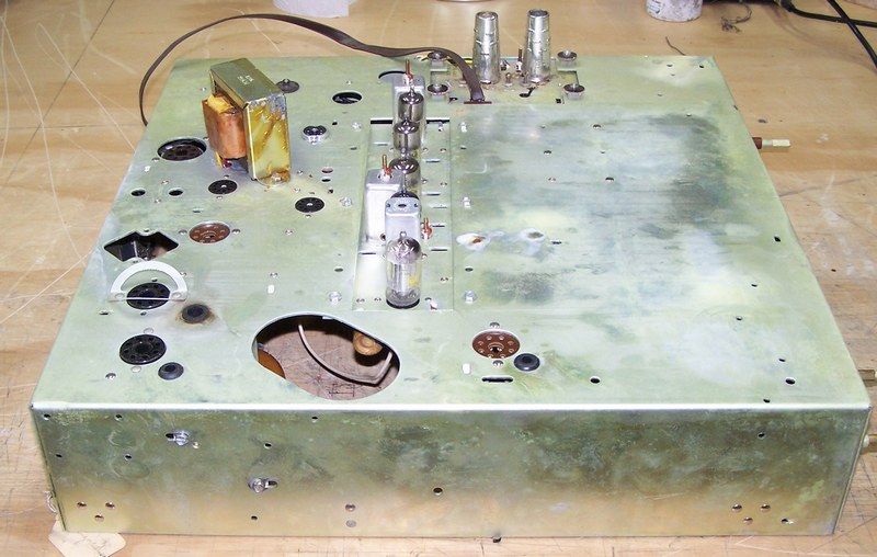 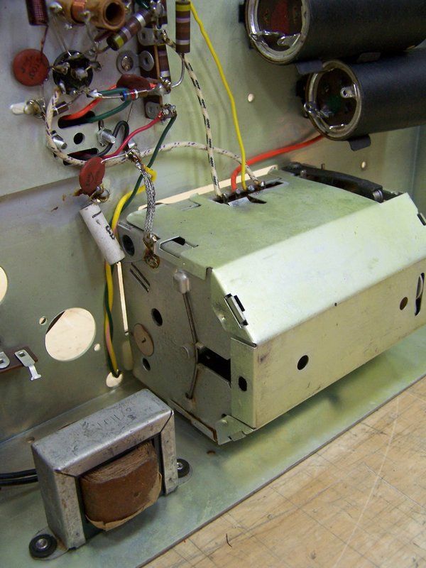 Here is a picture of the IF Strip from the bottom: 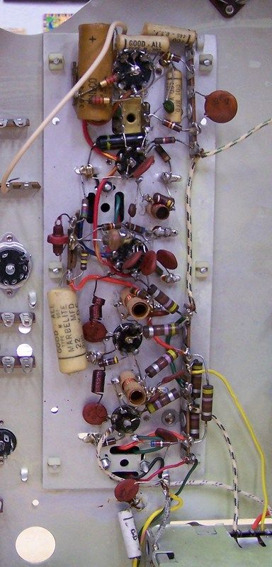 I did inventory and took a lot of pictures of each bag. That will be a separate post. Here is another view of the bottom of the chassis: 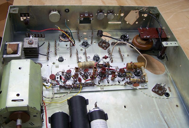 Here is proof that it was aligned: 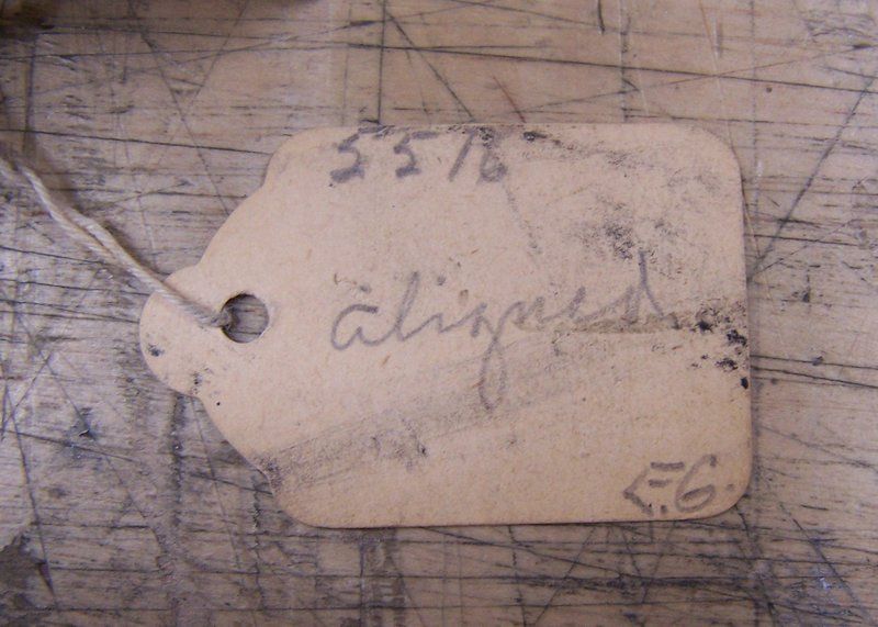
Last edited by Crist Rigott; 12-01-2016 at 10:49 PM. |
|
#40
|
|||
|
|||
|
I cleaned the chassis, yoke support, tuner, etc to get rid of the cad plating. I read somewhere that simple Green works great. It does! What I did was to pull the tuner, IF strip, filter caps, Selenium rectifier, fly back transformer, vertical output transformer, rubber grommets, all the pots, the HV rect. tube socket, etc. If I could unscrew it, it came off. This made the job a lot easier. I first masked off the tube sockets both top and bottom, then I would spray on some cleaner and then rub it around then after a few seconds I used a terry cloth to scrub and wipe the chassis clean. In reality, not much scrubbing. I also would use an acid brush and Q-Tips where needed. Once cleaned I would do the same thing again only with rubbing alcohol to further clean the metal.
Once that was done both top and bottom, I then used some Brasso to "even" out the look of the metal. Only this was done on the top, sides, and both sides of the yoke support. After that I wiped down the metal with WD-40. I then installed new rubber grommets. Here are some pics now that I'm done. Here is the bottom of the chassis with everything installed back in that is going to get installed for now. 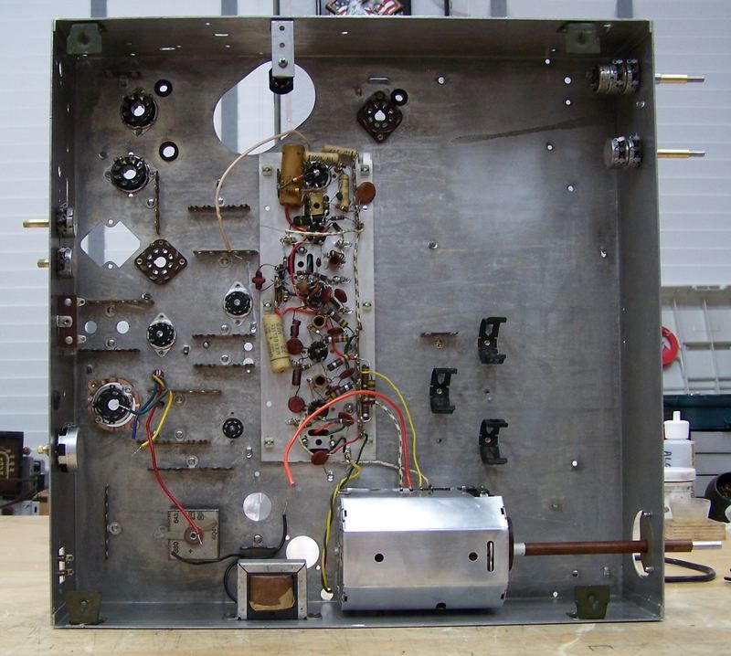 Here are some different views of where I am : 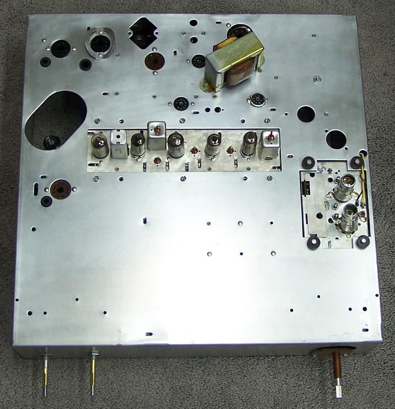 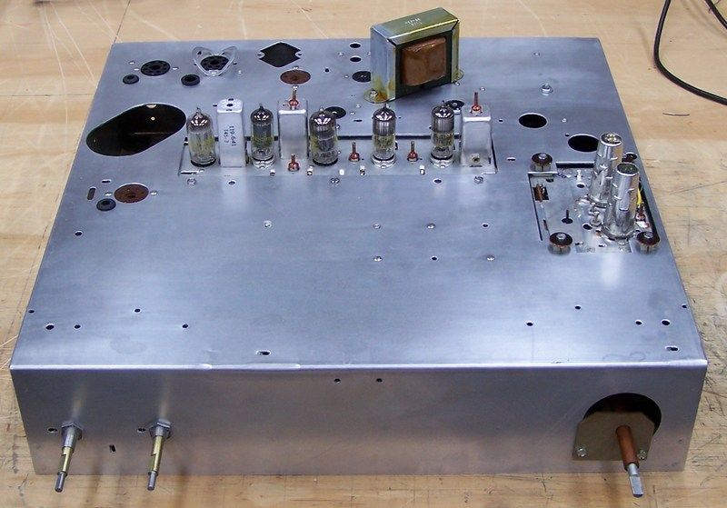 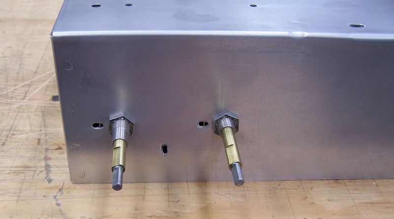 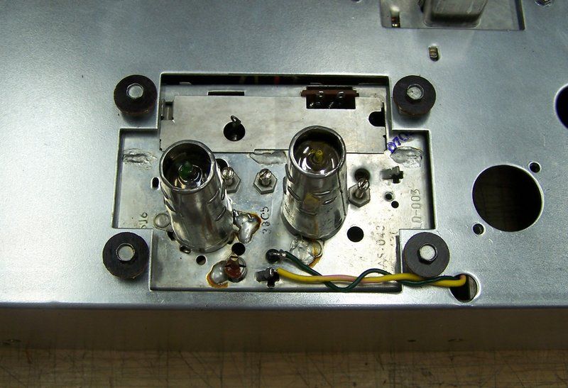 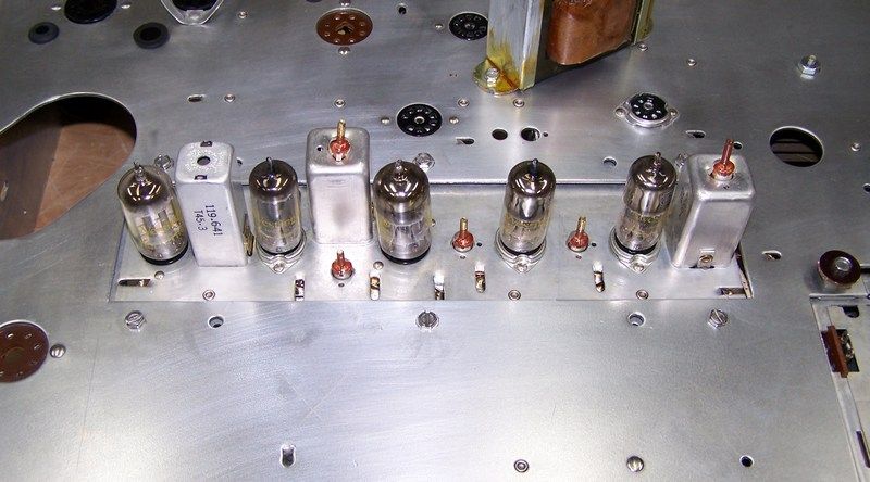 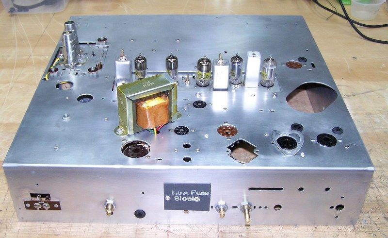 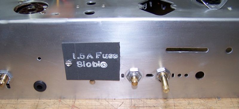 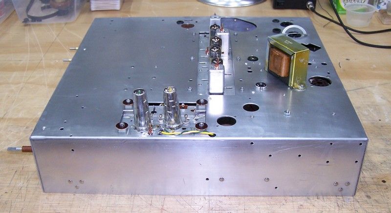
Last edited by Crist Rigott; 12-02-2016 at 10:34 AM. |
| Audiokarma |
|
#41
|
|||
|
|||
|
While I had the tuner out, it was cleaned and then the turret strips were cleaned and the whole thing cleaned and lubed and reassembled.
|
|
#42
|
|||
|
|||
|
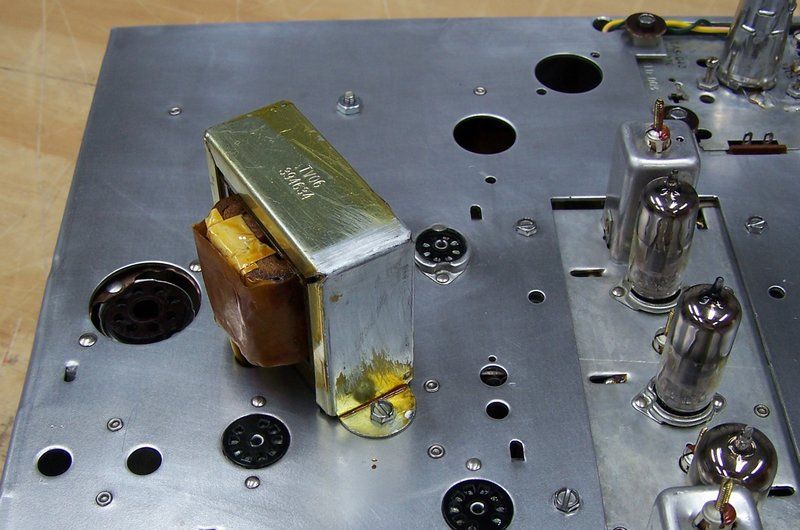
Anybody know what the VOT is coated with? It looks like varnish. The frame had some corrosion on it so I sanded it off, but now I need to re-coat it.
Last edited by Crist Rigott; 12-02-2016 at 10:31 AM. |
|
#43
|
||||
|
||||
|
Nice cleaning job! The transformer was likely dipped in insulating varnish after assembly.
I hope you were careful cleaning that chassis, as that yellow cadmium corrosion is pretty toxic stuff.... |
|
#44
|
||||
|
||||
|
Quote:
The yellow-green patina is harmless to electronics undisturbed, but the chromate is toxic, so removing it from something handled so often was wise. We used to spray Humiseal on just-cleaned CADPLAD chassis to keep it from corroding - spray clear krylon (remove tubes and cover sockets!) works well. Just dispose of your simple green rags in the trash - the concentration doesn't rise to hazmat levels.
__________________
Brian USN RET (Avionics / Cal) CET- Consumer Repair and Avionics ('88) "Capacitor Cosmetologist since '79" When fuses go to work, they quit! |
|
#45
|
|||
|
|||
|
Quote:
Yup, I was careful. |
| Audiokarma |
 |
| Thread Tools | |
| Display Modes | |
|
|