
|
|
|
#16
 11-14-2011, 11:03 PM
|
||||
|
||||
|
When the gether turns white it means the tube has lost it's vacuum, and tubes can NOT function once the vacuum is lost.
That is a nice set! I think I have the tuner and some parts off of a similar model if you need them.
__________________
Tom C. Zenith: The quality stays in EVEN after the name falls off! What I want. --> http://www.videokarma.org/showpost.p...62&postcount=4 
|
|
#17
11-15-2011, 07:22 AM
|
|||
|
|||
|
Quote:
Ebay shows them to be pretty pricey yap 
|
|
#19
11-15-2011, 09:11 PM
|
|||
|
|||
|
Quote:
I see about 5 of those white caps on the chassis, including one large one in the vertical circuit.
|
|
#21
11-15-2011, 10:12 PM
|
||||
|
||||
|
Bumblebee caps are in molded black plastic cases and the values are colore coded on them like resistors (some are much bigger than any color coded resistor which is a visual give away). I believe that "big Chiefs" are molded plastic as well but do not have the color code stripes. Plastic Molded paper capacitors come in many colors and trade names and are easy to spot once you know what they generaly look like (or by tracing the schematic if you are good at doing so).
I wish I had time to snap some photos of some bumblebees, and other types I've replaced to show you, but I'm sure the other will do that soon.
__________________
Tom C. Zenith: The quality stays in EVEN after the name falls off! What I want. --> http://www.videokarma.org/showpost.p...62&postcount=4
|
|
#22
11-15-2011, 10:21 PM
|
||||
|
||||
|
This article has basic info about recapping, with photos and descriptions of common capacitor types:
http://antiqueradio.org/recap.htm I don't know what's in those old white tubular caps, but I agree, those are iffy, too. Regards, Phil Nelson Phil's Old Radios http://antiqueradio.org/index.html
|
|
#23
11-16-2011, 09:30 AM
|
|||
|
|||
|
Are the large electrolytic capacitors really that expensive?
I mean one filter capacitor 160MFD(uF) 250 volts at mouser or digikey is around 22 dollars? I think since the set powers up, Im gonna replace the bad tubes first, and see how the picture tube is, if its OK I will start to replace the big caps and the other ones, I just won't run the set long or worry about picture problems until they are replaced. I don't have a CRT or tube tester. There are many plastic coated paper caps underneath the chassis, I have the schematic but I guess it takes considerable time to cross reference all of them? What kind of time you guys spending doing that?
|
|
#24
11-16-2011, 11:49 AM
|
||||
|
||||
|
As noted in the recapping article, with electrolytics it's often OK to go up to the next common higher capacitance value. For instance, if the original cap is 18 mfd (an oddball value), then you can use 22 mfd (a common value).
Same deal with voltage rating. It's OK to go somewhat higher. For instance, if the original cap is rated for 160V, then you can use one rated 250V. I don't know where you're looking on Mouser, but electrolytics are generally a few dollars each. Another good supplier is http://www.justradios.com/ , located in Canada. If you look at their listings of what's available, you'll get an idea of what is a common value and what is not. 160 mfd is not very often used nowadays. To get that value, you could combine, say, 100 mfd and 68 mfd in parallel (again, read the article). You could also bump up to 220 mfd if that's the nearest common value. Yes, color TVs are complex and it may take you a while to learn your way around that chassis and schematic. I don't count the hours I spend in a restoration because I do it for fun. Realistically, this is not something you can expect to polish off in one evening. So, I would relax, take my time, and enjoy the process of bringing a great old TV back to life. Regards, Phil Nelson Phil's Old Radios http://antiqueradio.org/index.html Last edited by Phil Nelson; 11-16-2011 at 11:55 AM.
|
|
#25
11-16-2011, 05:14 PM
|
|||
|
|||
|
Quote:
Thanks for the site/info! Helps a lot!
|
| Audiokarma |
|
#26
11-16-2011, 10:04 PM
|
||||
|
||||
|
Your new capacitors will look different than the old ones, since technology has improved and they are now a lot smaller. The linked article may explain it, but basically you can leave the old filter cans in place and mount the new electrolytics under the chassis. (don't leave the old ones wired in, though) You can get new can-type caps but those are expensive; maybe that was what you saw when you were shopping. Get electrolytics rated at 105c instead of 85c as they will last longer but won't cost much more.
__________________
Bryan
|
|
#27
11-16-2011, 10:59 PM
|
|||
|
|||
|
you can also save by using radial leads vs axial leads, a lot cheaper. I generally get nichicon's 105c rated. Check voltages, often you can get a 350v for the same as a 200v so if you need a 200v just get 350's that way you have them when a circuit requires a 300 or 350v. the also come in a variety of sizes, I like the tall skinny radials since they fit inside the old cans (I prefer to restuff the cans vs putting them in under the chassis). I have a method that I use when not too concerned about cosmetics. I have what I call a bone saw which has a receiprocating blade about 2" long. I 1st cover the chassis with paper around the can, then use the saw to cut if off just above the shoulder (about 1/4 inch from the bottom). the paper is there to catch the alum chips from the saw action. cutting at the shoulder leaves the phenolic base (which has the terminals of the can embedded in it) intact. then drill from the bottom side right along the term strips. with a center hold drilled for the common negatives. A little planning here can help to make sure the leads from the caps are in a position to allow all the caps to fit inside (up to 4) the can. Care needs to be applied to make sure the leads are next to terminals and not shorting to the chassis, there is not a lot of room for error, but its not hard. Triple check the polarity and the correct cap the correct term on the can.
by doing the above you can leave the lead dress alone as well as any parts soldered to the lugs (like resistors). I find that alone worth the effort as you don't have to spend time removing the old can and all the attached wires and parts. a typical can cap can be restuffed in about 5-10 min tops after you get the hang of how to use the saw and how to align the caps. The tall skinny ones make it much easier since they fit so easy inside the can. for the common neg I just pig tail some solid copper wire, slide it over the common leads in the center, solder, then solder the wire to one of the already solder cap twist lock lugs. I leave the insulation in place just so its not as critical to make sure the wire does not brush up against term on the cap. again rechecking work catches this stuff (I have a very bright shop light handy for that). after all that is done I will do a slow start with a variac, monitoring the B+ voltage and current. slowly ramping it up will make sure there were no reversed caps or shorts to worry about. if all good then I will use a large threaded hook screw into the old cap guts, pull them out, clean the inside bottom edge of the can with some solvent, scratch it up with some 150 grit sand paper, smear some 5 min epoxy around the inside edge, positiion the can over over the base (with values pointing out so they can be read) and let gravity pull the epoxy downward and flow around the base. the 5 min is good since it's pretty thick stuff. I will also cut some alum tape (used by hvac folks) into strips about 1/2 wide and use that to join around the shoulder, just in case some of the epoxy manages to seep out the seam. again this is not cosmetically the best but it is fast, and IMHO the least disruptive to the overall chassis (since the bottom terminals are left completely alone, but for the new cap leads solder to them. I take the same approach on recapping hand wired chassis, leaving the existing leads alone where they attach to tube sockets, just pig tailing the new parts in. The main reason is to properly remove the old solder and unwrap the orig leads can be some what stressful to the terms, esp on old wafer style sockets. the pig tailing done well does not look bad and certainly is a lot less stressful. now if I was doing a museum quality restoration then I would no doubt take a different approach, but for daily drivers, esp if they do not belong to me, I go the do no harm approach even if it is not as pretty.
|
|
#28
11-17-2011, 07:27 PM
|
||||
|
||||
|
Daave: "Are the large electrolytic capacitors really that expensive?"
Another source for electrolytics are BPC's (90's TV's) and monitors. I recycle them at the county "dump" facility, BUT only after i snip leads and pull out the chassis. Monitors have a few 160 volt caps from 47 to 200 mfd and I hide these under many a radio chassis. Junk black box Tv's get the same treatment and there are usually caps up to 350 volts. Your Zenith will need some in the 450 volt range and those do cost some $$$. Check the schematic to see what voltage is really needed rather than going by the OEM cap. Good luck, Dave
|
|
#29
11-18-2011, 02:53 PM
|
||||
|
||||
|
Oh, i almost forgot: One of the most important things I learned about capacitor voltages involves the fact that AC voltages on the plate feedback circuit of vertical output tubes can far exceed the DC voltage. On most schematics, it says "do not measure", yet an OEM 600volt cap is feeding back to the vertical in a multi-vibrator configuration. These caps should be 1600 volts minimum. Many a Philco BW recap and subsequent vertical collapse taught me this lesson.
|
|
#30
12-07-2011, 09:03 PM
|
|||
|
|||
|
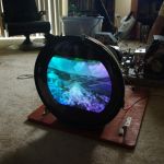
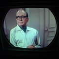
OK well I finally got a couple new tubes for this TV, and well, not sure the CRT is much good. It does have a full raster now, but no sound, VHF and UHF tuners work, but for the life of me I can't get it to tune a colour picture.
The G2 controls have to be almost all the way up to get any brightness, and the focus control won't dial in a sharp focus. All the filter electrolytics are still original and are cold after even a few hours of running. The contrast control doesn't do anything, brightness as well has 3/4 of its control that just produces a black picture. So not terribly excited right now. Does anyone think I have any hope on a CRT rebuilder helping this tube? Its never had a brightener installed. Some pics.
|
| Audiokarma |
 |
| Thread Tools | |
| Display Modes | |
|
|


 Linear Mode

