
 |
|
|
|
#1
|
|||
|
|||
|
Quote:
Oracal 631 Light Grey #631-072 H&H Sign Supply Company http://www.hhsignsupply.com/productc...-538p44760.htm I also tried Oracal 651 Light Grey and Silver Grey |
|
#2
|
||||
|
||||
|
Steel wool can work havoc if the fine wires get into things. Inspect closely and be sure they're not in there.
__________________
Reece Perfection is hard to reach with a screwdriver. |
|
#3
|
|||
|
|||
|
10-4
|
|
#4
|
|||
|
|||
|
I'm pretty much done cleaning up the chassis top. I still have to do underneath. I didn't use the steel wool. It started to shed and I didn't want those little shavings getting everywhere.
I did remove the big solder blobs that were at each adjustable coil. these will be re-soldered, but neatly this time. 
Last edited by Crist Rigott; 02-09-2017 at 11:02 AM. |
|
#5
|
|||
|
|||
|
I cleaned up the adjustable coils on the top of the chassis in preparation to solder the caps to the chassis. I used my 150 soldering iron to apply a small amount of solder to form a nice fillet.
 I then noticed that the hold down screws on T107 were over torqued. It looks awful.  So I pulled the transformer and disassembled it. I straightened the screws. While I had it apart I dusted it off and cleaned it gently with some alcohol. These pics are before I cleaned the coil.   I reassembled the transformer and cleaned up the case and terminals. Ready to install.  Re-installed and ready to wire. I'll do that later while I'm recapping etc. I also cleaned up the case on T108.  Next up will be to paint the top transformer cover. The transformer underneath looks very good. My order from Digikey came in already and while the transformer paint is drying, I'll re-stuff the caps. |
| Audiokarma |
|
#6
|
|||
|
|||
|
Time to re-stuff the E-Caps!
There are 5 of them. The ones that came off the set are on the left and what I'm going to use is on the right. 4 of them use the cardboard covers. One cardboard cover on a shorter caps was already removed when somebody did the partial restoration. What I plan on doing is to use 5 new bases because I don't want the twisty mounting ears to break off when installing them in the chassis. The cans that use the cardboard covers will be cut off about 1/2 above the base. Then I'll epoxy a PVC sleeve to the base. Install the new caps and slide on the cutoff can. Then slide on the cardboard cover. The 1 E-Cap that does not have a cover, the can will be cut off right at the base. The base and can will be trued up and again a PVC sleeve will be epoxied to the base. I'll install the new caps, and slide on the polished up can. I'm using all Nichicon 105 degree caps and most are at least 10,000 hour caps. 
|
|
#7
|
||||
|
||||
|
That chassis looks great all cleaned up. Was just thinking, if makers of slug-tuned radio IF transformers had made them that way, with the little ceramic caps instead of the silver mica jobs, we wouldn't have SMD today. But I'm sure it would have cost more.
__________________
Reece Perfection is hard to reach with a screwdriver. |
|
#8
|
|||
|
|||
|
Right! As I'm working on this TV, I have noticed the "step up" on the quality of the design. That coil was beefy and well made.
|
|
#9
|
|||
|
|||
|
I started by cutting of the base of the donor cap for the tall uncovered capacitor (C116). I use my band saw and shim the can up from the table of the saw using a piece of 1/16 plywood. This gives me a more even cut.
  Then on the 4 other donor caps I marked up from the base 3/8. I know I said 1/2 but 3/8 will work just as good.  Here is what it looks like inside of the donor caps after cutting off the bases.  And a shot after I removed the guts from them.  Then I took the old uncovered C116 and cut its base off as low as I can go. You can see a little bit of the phenolic base still attached to the upper cans guts.  C116 the tall uncovered cap with its guts pulled.  The other 2 tall covered E-caps (C127 and C128) with the bases cut off. These bases were cut off with a 3/8 lip to them so that when these cans are mated to the donor bases they will be the correct height.  Here C127 and C128 with their guts pulled.  And finally here is the line up of the 5 E-Caps. L to R are the 2 short covered ones C131 and C132, then the 2 tall covered ones C127 and C128, and finally the tall uncovered cap C116. 
Last edited by Crist Rigott; 02-11-2017 at 09:25 PM. |
|
#10
|
|||
|
|||
|
I cleaned and deburred the cans and bases.
I then made the PVC sleeves from PVC pipe I got at the Home Depot. I true up 1 end on my disc sander using the 90 degree guide. Then I mark the trued end with an arrow. This is the end that will be glued to the base. I true that end up so the can will stick straight on the assembly. I then mark off a 1 inch cut line and cut it off using my band saw. I then clean up both ends using my #11 hobby knife and sandpaper. This is repeated for all 5 sleeves.  The sleeves are then epoxied to the bases using 15 minute epoxy. I only apply the epoxy to the edge that will rest on the bottom in the base. In the case of C116 were the base is cut off even, I visually align the sleeve to the base. I then made up my capacitor assemblies. I used Nichicon 105 degree caps that I get from Digikey. The caps are hot glued together and wired using 6oo volt wire. The assembly is put into position in the base and the the insulation of the wires are marked. The assembly is removed from the base and the wires are stripped at the marks. I use hot glue to glue the caps into the bases. I usually glob on a big dollop and then insert the caps into the bases. This is allowed to set up and the the wires are soldered to the proper terminal. The ground wire is left unconnected till the cap is inserted into the chassis, then it is soldered to a twisty tab. Here is a picture of C127. BTW, I used 47uf caps instead of the 40uf called for, a 22uf instead of the 20uf, a 82uf instead of the 80uf, and a 270uf instead of the 250uf.  Here is a picture of C116 before the caps are inserted into the base. It has 4 caps.  Another view.  The base of C116 with the wires soldered to the terminal.  Top side of C116. 
|
| Audiokarma |
|
#11
|
||||
|
||||
|
Crist, What kind of blade you have in your band saw that cuts those cans so smoothly? Or have you already cleaned and de-burred your donor cans before you took those first pictures.

|
|
#12
|
||||
|
||||
|
That's probably adhesive used to hold the rubber in place. There would be no need for it to be conductive. There are little springs there to contact the aquadag on the outside of the picture tube, which is the only thing I would think would be of concern from an electrical conductivity point of view.
|
|
#13
|
|||
|
|||
|
Quote:
|
|
#14
|
|||
|
|||
|
I started putting things back together today.
I cleaned and painted the volume pot and cover because the tin plating was well worn in areas. This pot is in full view with the chassis out of the cabinet so I wanted it to look good. One of the wires had a very old piece of friction tape on it and sure enough the wire was spliced. I cut it off at the splice and followed it down into the chassis. I cut the wire and spliced in about a 4 inch piece of wire. This way the original wire came out of the top of the chassis while the extra length wire that was spliced is hidden under the chassis. If you look close into the tuner hole, you'll see some black heat shrink where one end of the wire was spliced. The other end is just inside the chassis. I used some clear heat shrink over the fraying cloth insulation on the pot element and wiper wires to neaten them up. 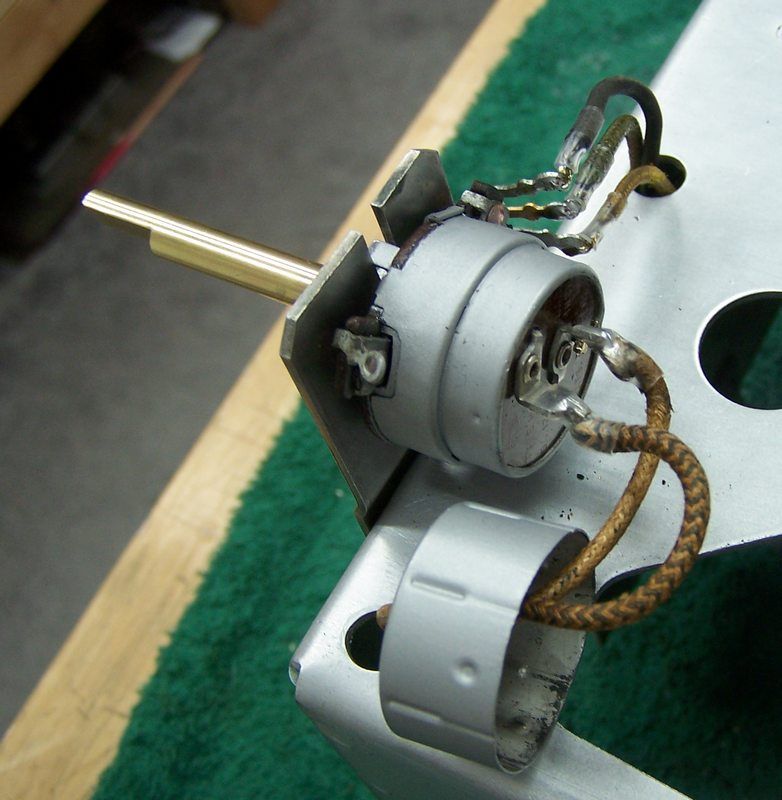 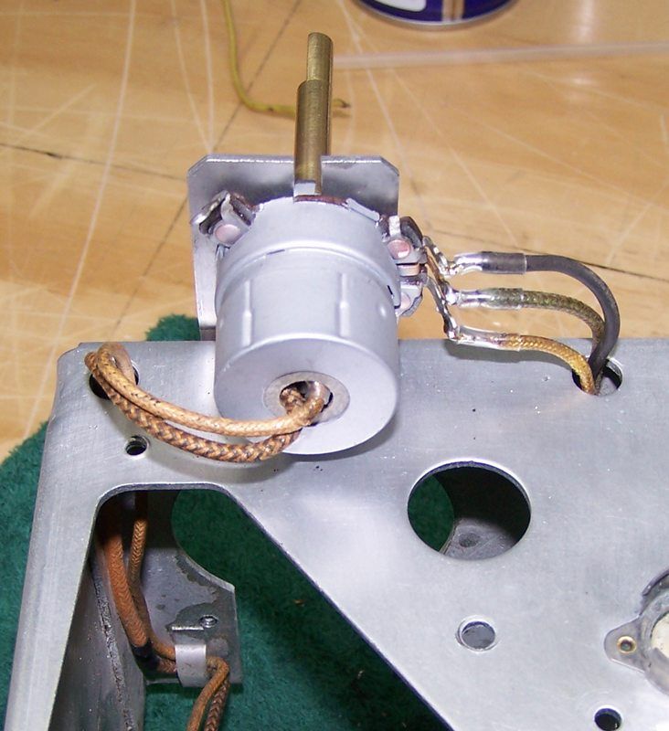 Next up was the Brightness and Picture (contrast) pot. Pretty tight quarters. Black heat shrink was used here because the wires are hidden under the box. 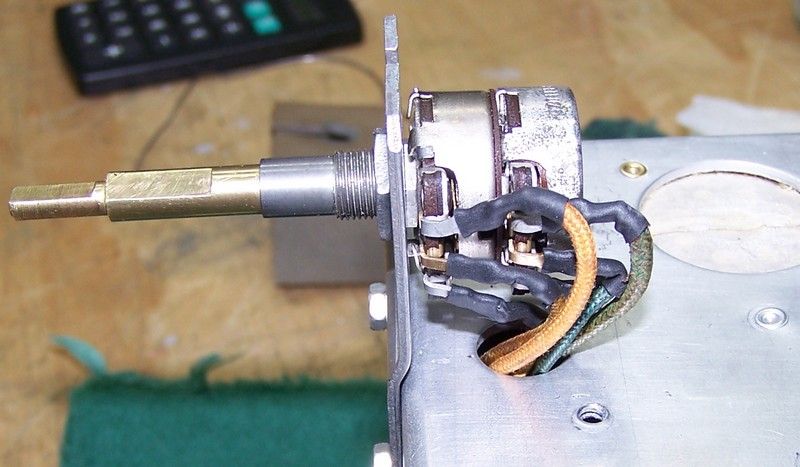 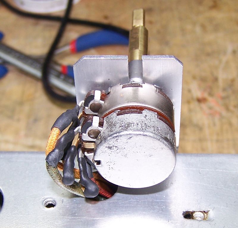 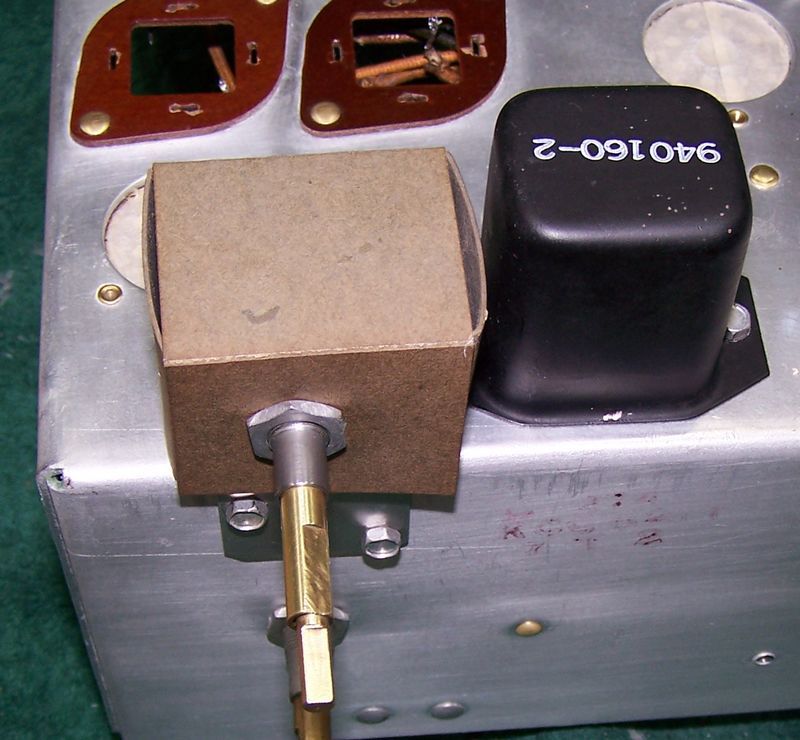
|
|
#15
|
|||
|
|||
|
It's been a few days since the last post.
I cleaned up and painted the bleeder resistor housing and re-installed it and wired it back up. Note that I use a small piece if 1/8 clear heat shrink on the ends of the cloth covered wire to "tidy" up the end. It keeps the insulation from fraying all over the place and messy looking. 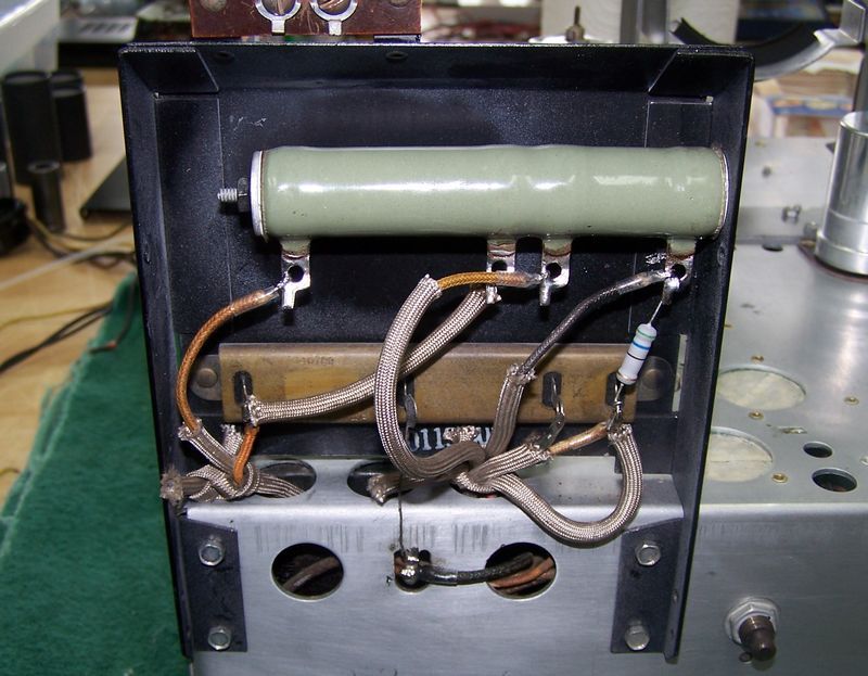 Here are some pictures of sections of the wiring underneath. Not very good and low skill level of the person who attempted to do a previous restoration on this TV. Disc caps where tubulars and micas go! He used the hook method when he wasn't winding the lead on. 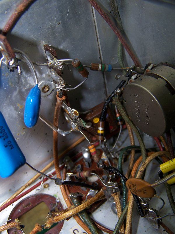 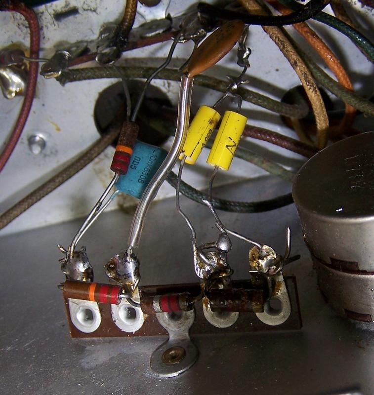 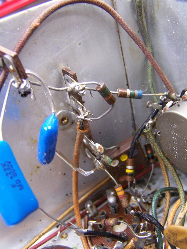
|
| Audiokarma |
 |
|
|