Thanks guys!
Splitting text past the 16 pic limit above.
I wanted to do the horizontal setup. but I could not really get video through the set with my ch13 basement modulator...I was able to get what looked like weak fuzzy sync bars and it looked like the horizontal was off freq. And I could get video waveforms on the bench, but no video with the chassis in the cabinet. I began to realize I was chasing my tail: I could not scope the Horizontal section and completely adjust it (can't adjust it is your not sure it is on frequency) in the cabinet or drive the set with my other bench equipment, but with the deflection disabled on the bench the AGC was probably being affected and there was no CRT to confirm injected or received video was being handled appropriately.
I then grabbed a test jig given to me by Dieseljeep and began trying to figure out how to connect it...There was no listing for the CTC-2B in 2 of the manuals I skimmed, and the adapters I have are mostly solid state era with some tube rectangular mixed in....Combing through I found an adapter that I recognized is for the yoke of a Zenith 15Y6C15 (a set in my collection) I was able with the Zenith schematic to decipher the adapter wiring color code and make a new yoke adapter for the CTC-2B (I can post up the pinout if anyone is curious). From there the HV and CRT connections were straightforward, and dynamic convergence I outright skipped connecting.
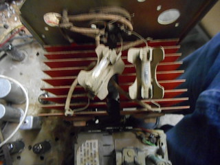
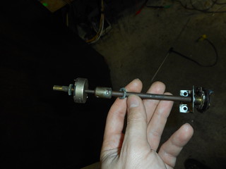
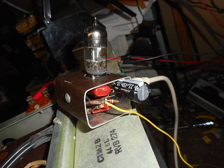
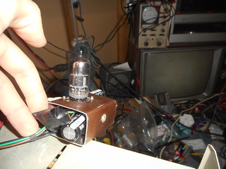
H out cathode current was down a lot VS its value with the correct yoke, and if the HV was connected to the jig there were some concerning noises, but for 30 sec raster duration powerups, this was sufficient. I began testing tubes and injecting video with the B&K analyst...I quickly found that the lumina chain was dead before the 2nd video amp. Then I found the contrast pot was open and the carbon track at the ends was gone. I also solved the mystery of there being 2 contrast pots on the shaft, but the front pot only using 1 lug. comparing the Sam's I was working off of to the RCA service clinic I found my set's contrast circuit is an in-between design. The rear pot on the shaft (delay line output) is wired according to the RCA manual, but the front pot (secondary chroma gain) is omitted, but used as a terminal strip/tie point like in the Sam's. I found a usable pot, but unfortunately, I had to remove both pots since the Allen key set screws on the shaft coupler between pots is frozen. I've got a new pot cobbled in, but will probably need to revisit this. Here are pics of the original and my sloppy repair.

I did some more playing around with the B&K analyst injecting video and RF, and at one point noticed there were nice color bars from the analyst....I was SO focused on troubleshooting the IF's refusal to pass decent lumina that I turned off the distracting color on the analyst without thinking about what I was seeing

....About 30 minutes later during a restroom break, it finally hit me: "holey crap the color circuits are working, aren't they!?".

....
The color circuits seem to be working and in or somewhat close to proper adjustment.


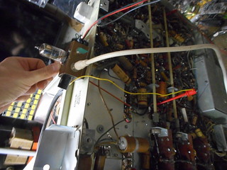
After checking that, I remembered something useful: Phil has an article about building a video amp for composite video injection for the CTC-2 on his site...I whipped one up last night and now have a good way to feed it video. I built it with a twist. I added a switch to go between IF and external video so if I can fix the RF/IF issue I can pick my input method.
With that I can finally tune the horizontal stage up and KNOW that it is in sync...Which is the plan going forward.
I also intend to check the tuner on a different channel for good measure.
I took over 100 pictures of it and don't feel like posting them 16 (VK's pictures per post limit) at a time so here is a link to the rest:
https://www.flickr.com/photos/137849...57690691153411 Lots of chassis pictures, and some more screenshots there.
A missed points from the cap rebuild discussion: on the tubular lytics I tried a new technique. I normally slice an end completely off, but found only slicing most of the way through leaves a nice hinge that keeps more structure in the rebuilt cap.

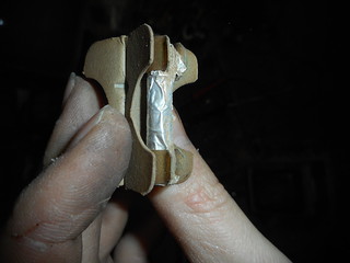
Someone had added piggyback fuse replacements. That seems normal till you notice they used higher amp fuses and the larger B+ fuse had a MacGuyver style replacement...When the Piggyback spare blew, they simply stuck some aluminum foil in parallel!


Only way they could have made it derpier is if they had used a foil gum wrapper instead of straight foil.